
Rotating mechanism of ship unloading machine
A technology of a slewing mechanism and a ship unloader, applied in the direction of cranes, etc., can solve the problems of large model, size and weight, high cost, insufficient bearing capacity, etc., and achieve the effect of light weight, low price and simple structure
- Summary
- Abstract
- Description
- Claims
- Application Information
AI Technical Summary
Problems solved by technology
Method used
Image

Examples
Embodiment Construction
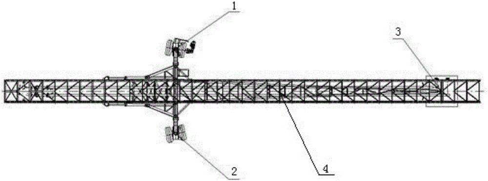
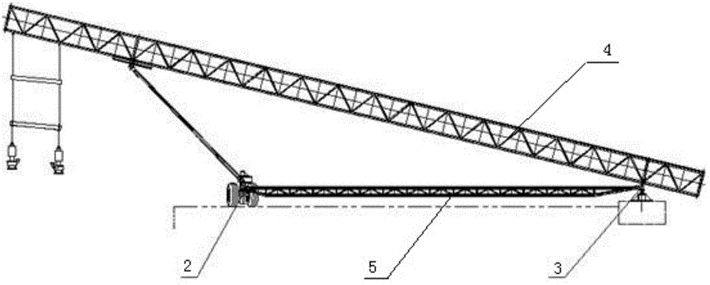
[0024] Such as Figure 1 to Figure 5 As shown, a slewing mechanism of a ship unloader includes a slewing traveling carriage 5, a wheel set device and a slewing pivot device 3 installed at the front and rear ends of the slewing traveling carriage 5; the slewing pivot device 3 includes a slewing The pivot support 32 and the pivot 31 assembled in the shaft hole at the top of the pivot support 32; the bottom of the pivot support 32 is fixedly installed on the dock foundation.
[0025] Such as Figure 5 As shown, the lug structure on the upper part of the rotary pivot 31 is respectively connected and fixed with the rear end of the rotary traveling frame 5 and the unloading arm 4 of the ship unloader, so that the rotary traveling frame 5 and the unloading arm 4 can pass through The swivel pivot 31 rotates 360° around the swivel pivot support 32 .
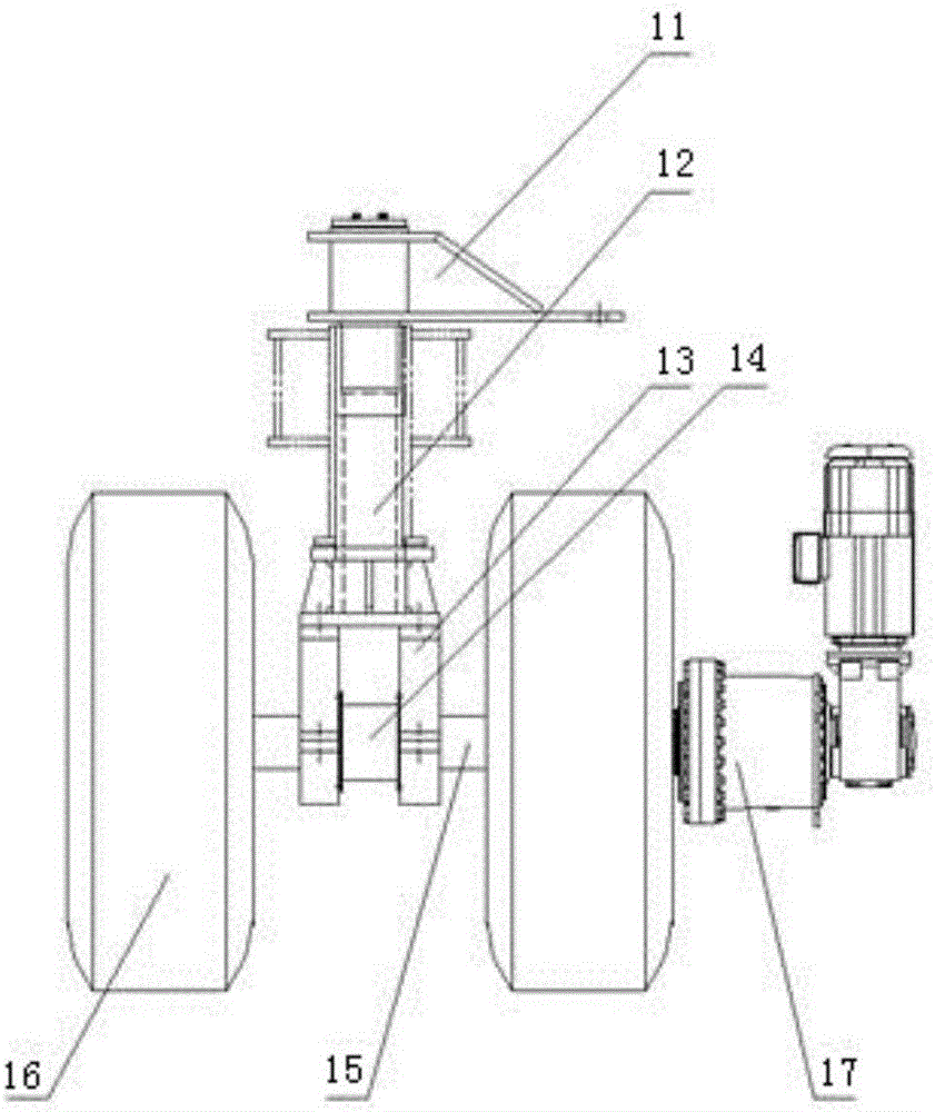
[0026] The wheel set device has two groups, which are respectively arranged on both sides of the front end of the slewing traveling ca...
PUM
 Abstract
Description
Claims
Application Information