A capping device, packaging equipment and filling production line

A technology of pressing caps and pressing rods, which is applied in the direction of flanged bottle caps, etc., can solve the problems of drug pollution, large gaps in cleanliness standards, complex structures, etc., and achieve high safety and stability.

Active Publication Date: 2019-05-03
湖南华尔特今朝科技有限公司
View PDF7 Cites 0 Cited by
  • Summary
  • Abstract
  • Description
  • Claims
  • Application Information

AI Technical Summary

Problems solved by technology

Especially in the filling practice of medicines, the researchers of the applicant found that there are at least the following problems in the above-mentioned prior art: 1) The structure is complex; 2) The transmission and power of the capping mechanism are generally located at the position of the operated The upper or oblique upper part of the object, especially the bearing with relative sliding, or the joint between the roller and the cam groove is prone to produce pollutants that pollute the medicine, such as lubricants, etc. Compared with the increasing cleanliness standards, the gap is getting wider and wider

Method used


Image

  • A capping device, packaging equipment and filling production line
  • A capping device, packaging equipment and filling production line
  • A capping device, packaging equipment and filling production line

Examples


Embodiment Construction

[0040] In order to enable those skilled in the art to better understand the various technical solutions involved in the present invention, the present invention will be further described in detail below in conjunction with the accompanying drawings and specific embodiments. It should be noted that, in the case of no conflict, the embodiments in this application and the specific technical features described in the embodiments can be combined in any suitable way; The possible combinations are not further described, as long as they do not violate the idea of ​​the present invention, they should also be regarded as the content disclosed in the present invention.

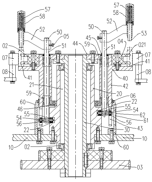
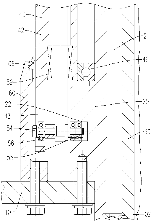
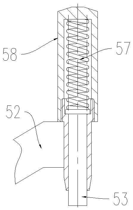
[0041] like figure 1 , figure 2 , image 3 , Figure 4 and Figure 5 as shown, figure 1 A schematic cross-sectional view of the structural principle of the capping device provided by a specific embodiment of the present invention; figure 2 for figure 1 The partially enlarged cross-sectional schematic diagram of ...


PUM


Abstract

The invention discloses a gland device which comprises a platen, a driving shaft, a turntable, gland mechanisms and a sealing ring base, wherein a bearing base is arranged on the platen; an axle hole and a cam slot are formed in the bearing base; the driving shaft is penetrated through the axle hole; a driving wheel is arranged on the lower part of the driving shaft while the turntable is arranged on the upper part; a stirring wheel and a bottle-bearing surface are arranged on the turntable; the lower part of the turntable extends to the position of the cam slot and is equipped with a vertical guide slot; the gland mechanisms are uniformly distributed on the periphery of the turntable; each of the gland mechanisms comprises a lifting shaft, a pressing rod support arm and a pressing rod; a roller shaft is arranged at the lower end of the lifting shaft; a No.1 roller is arranged at one end of the roller shaft while a No.2 roller is arranged at the other end, so that the pressing rod can fully automatic complete the gland operation in the rotating process of the turntable; the sealing ring base is arranged on the platen and upward extends in a cylindrical form; a first dustproof sealing ring is arranged on the upper part of the sealing ring base; the first dustproof sealing ring is located above the guide slot and is matched with the turntable. The gland device has the technical advantages of less pollution and high reliability. Besides, the invention also provides a filling production line and a packaging device adopting the gland device.

Description

technical field [0001] The present application relates to the technical field of filling production, and in particular to a capping device, which is mainly used in preparation equipment for medicine, food, cosmetic liquid and the like. For example, it is used in filling machines and packaging equipment for filling food, medicine and health care products. [0002] In addition, the present application also relates to a packaging device using the above capping device. [0003] In addition, the present application also relates to a filling production line using the above capping device. Background technique [0004] In the existing filling production line or packaging equipment containing the capping mechanism. For example, the authorized announcement number is a kind of multi-purpose filling and sealing machine provided by the Chinese utility model patent of CN2300641 Y, and the a kind of filling and capping device provided by the Chinese utility model patent of CN 205222640 ...

Claims


Application Information

Patent Timeline
Patent Type & Authority Patents(China)
IPC IPC(8): B67B3/02
CPCB67B3/02
Inventor 唐忠华屈志文冯涛
Owner 湖南华尔特今朝科技有限公司
Why Eureka
Try Eureka