
Rotary rake type grid dirt removing equipment

A grid decontamination and equipment technology, applied in the direction of water/sewage treatment, water/sludge/sewage treatment, chemical instruments and methods, etc., can solve the problem of easy accumulation of debris on the grid, non-adjustable installation angle, attached grid Easy to clog and other problems, to achieve the effect of reducing labor intensity, reducing labor costs, and reducing cleaning frequency

Pending Publication Date: 2017-02-22
CHONGQING VOLIK ENVIRONMENTAL PROTECTION EQUIP CO LTD
View PDF4 Cites 1 Cited by
  • Summary
  • Abstract
  • Description
  • Claims
  • Application Information

AI Technical Summary

Problems solved by technology

[0007] The problem to be solved by the present invention is to provide a rotary rake type grid decontamination equipment for the above-mentioned deficiencies in the prior art, which solves the problem of traditional equipment installation by improving the frame and setting iron baffles at the bottom of the frame. The angle cannot be adjusted. At the same time, both the main grid and the auxiliary grid are set in a circular structure, which solves the technical problem that the traditional grid is easy to accumulate sundries. At the same time, the slag scraping unit is designed to solve the problem of the traditional auxiliary grid being easily blocked. technical issues

Method used


Image

  • Rotary rake type grid dirt removing equipment
  • Rotary rake type grid dirt removing equipment
  • Rotary rake type grid dirt removing equipment

Examples


Embodiment Construction

[0025] In order to make the technical means, creative features, goals and functions achieved by the present invention clearer and easier to understand, the present invention will be further elaborated below in conjunction with the accompanying drawings and specific embodiments:

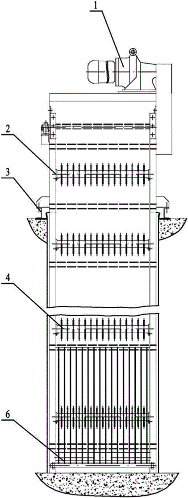
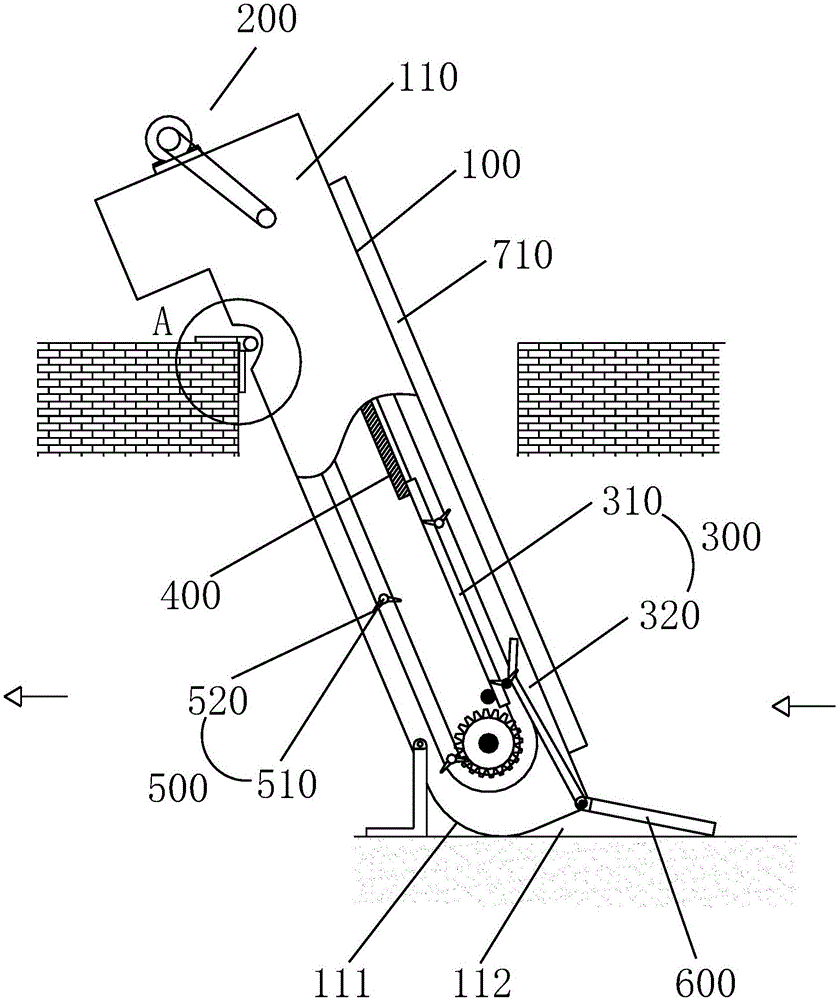
[0026] refer to Figure 3-4 with Image 6 , Figure 8 with Figure 9 , the present invention proposes a rotary rake type grid decontamination equipment, including a frame 100 and a slag blocking unit 300 arranged on the frame 100, and a slag scraping unit 700 is also arranged on the frame; wherein

[0027] The frame 100 includes two opposite side panels 110, the bottom edges of the two side panels 110 are at right angles to the front side edges, and the bottom edges of the two side panels 110 are excessively connected to the back side edges by an arc edge 111. ;

[0028] The slag blocking unit 300 is arranged at the middle and lower part of the frame 100, and includes a main grid body 310 and an a...


PUM


Abstract

The invention provides rotary rake type grid dirt removing equipment. The rotary rake type grid dirt removing equipment comprises a rack, and a dreg intercepting unit and a dreg scraping unit which are arranged on the rack, wherein the dreg intercepting unit is arranged at the lower middle part of the rack; the rack comprises two side plates which are arranged oppositely; the bottom edges of the two side plates are in transition connection with the back side edges of the two side plates through arc-shaped edges; the dreg intercepting unit comprises a main grid body and a secondary grid body arranged between the two side plates; the main grid body comprises a plurality of cylindrical main grid bars which are parallel to one another; the secondary grid body is close to the lower end of the rack and comprises secondary grid bars with the quantity the same as that of the main grid bars; the secondary grid bars are round and the tail ends of the secondary grid bars are pivoted to one shaft; the front ends of the secondary grid bars are overlapped on the corresponding main grid bars; an iron baffle is pivoted to the shaft; and the iron baffle is as high as the side plates and the width of the iron baffle can cover an opening which is formed by the lower end of the rack and is formed between the two side plates. According to the rotary rake type grid dirt removing equipment provided by the invention, the bottom of the rack is improved and the iron baffle is arranged at the bottom of the rack, so that the problem that an installation angle of traditional equipment cannot be adjusted is solved.

Description

technical field [0001] The invention relates to the technical field of sewage treatment, in particular to a rotary rake type grid decontamination equipment. Background technique [0002] The rotary rake grill decontamination machine is a special equipment for water treatment that can continuously and automatically intercept and remove various shapes of debris in the fluid. It can be widely used in urban sewage treatment, tap water industry, and water inlets of power plants. It is a comparative One of the advanced solid-liquid screening equipment. [0003] The existing rotary rake grille decontamination machine generally has the following two structures: ① Use the ring-shaped rake tooth mesh belt to salvage the slag; ② Use the rake tooth mechanism arranged at intervals on the chain belt to salvage the slag. refer to Figure 1-2 As shown, it is a schematic diagram of the working process of the rotary rake type grid decontamination machine of the second existing structure. Wh...

Claims


Application Information

Patent Timeline
IPC IPC(8): C02F1/00
CPCC02F1/00
Inventor 陈文
Owner CHONGQING VOLIK ENVIRONMENTAL PROTECTION EQUIP CO LTD
Features
  • Generate Ideas
  • Intellectual Property
  • Life Sciences
  • Materials
  • Tech Scout
  • Unparalleled Data Quality
  • Higher Quality Content
  • 60% Fewer Hallucinations
Learn More