Axis-around operating structure of circular weft knitting machine
A technology of circular weft knitting machine and shaft center, applied in knitting, weft knitting, textile and paper making, etc., can solve the problems of poor radial and axial positioning accuracy, improve installation accuracy tolerance, save production costs, increase The effect of service life
- Summary
- Abstract
- Description
- Claims
- Application Information
AI Technical Summary
Problems solved by technology
Method used
Image
Examples
Embodiment 1
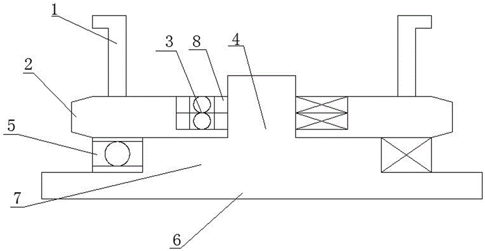
[0034] The invention proposes a circular knitting machine with a structure that revolves around the axis, which solves the shortcomings of poor radial and axial positioning accuracy when the tooth plate drives the needle cylinder in the prior art, and uses tapered roller bearings to adjust the radial and axial accuracy Control to effectively improve the radial and axial positioning accuracy of the needle cylinder during operation, such as figure 1 As shown, the following arrangement structure is adopted in particular: it includes a center column base, a shaft-circling bearing device and a tooth plate 2, the shaft-circling bearing device is nested on the center column base, and the tooth plate 2 is nested in the shaft-circling On the central bearing device, a bearing disc 8 is arranged on the bearing device around the shaft, and a tapered roller bearing 3 is arranged on the bearing disc 8 around the shaft.
[0035] When designing, the center column base is installed on the larg...
Embodiment 2
[0037]This embodiment is further optimized on the basis of the above-mentioned embodiments. Further, in order to better realize the present invention, the shaft-circling bearing device can be arranged on the center column base, and the shaft-circling bearing device can be mounted on the center column base. Make a circular horizontal rotation on the upper side, so that the main transmission teeth drive the crankshaft to transfer, such as figure 1 As shown, the following arrangement structure is adopted in particular: the center column base includes a center column 4, a column bearing plate 7 and a support platform 6, the central column 4 is arranged on the column bearing plate 7, and the column bearing plate 7 is arranged on On the support platform 6 , the 8 sets of bearing discs around the axis are set on the central column 4 .
[0038] When designing, the base of the center column is provided with a support platform 6, a column bearing plate 7 and a center column 4 in sequenc...
Embodiment 3
[0041] This embodiment is further optimized on the basis of any of the above-mentioned embodiments, further to better realize the present invention, so as to continue to carry the weight of the tooth plate; at the same time, reduce the wear between the large plate and the tooth plate and the load caused by wear increase, accuracy decreases, such as figure 1 As shown, the following arrangement structure is adopted in particular: a bearing carrying device is also arranged between the lower part of the crankset 2 and the support platform 6 .
PUM
 Abstract
Description
Claims
Application Information
 - R&D
- Intellectual Property
- Life Sciences
- Materials
- Tech Scout
- Unparalleled Data Quality
- Higher Quality Content
- 60% Fewer Hallucinations
Browse by: Latest US Patents, China's latest patents, Technical Efficacy Thesaurus, Application Domain, Technology Topic, Popular Technical Reports.
© 2025 PatSnap. All rights reserved.Legal|Privacy policy|Modern Slavery Act Transparency Statement|Sitemap|About US| Contact US: help@patsnap.com

