Rotating structure of circular knitting machine around the axis

A knitting circular weft machine and shaft center technology, applied in the field of knitting machinery technology and transmission, can solve the problems of poor radial and axial positioning accuracy, and achieve the effects of improving installation accuracy tolerance, reducing energy consumption and increasing service life

Active Publication Date: 2018-05-01
SICHUAN RES INST OF SILK SCI
View PDF10 Cites 0 Cited by
  • Summary
  • Abstract
  • Description
  • Claims
  • Application Information

AI Technical Summary

Problems solved by technology

[0013] The purpose of the present invention is to design a circular knitting machine with a structure that revolves around the axis to solve the shortcomings of poor radial and axial positioning accuracy when the tooth plate drives the needle cylinder in the prior art. The axial precision is controlled to effectively improve the radial and axial positioning accuracy of the needle cylinder during operation

Method used


Image

  • Rotating structure of circular knitting machine around the axis

Examples


Embodiment 1

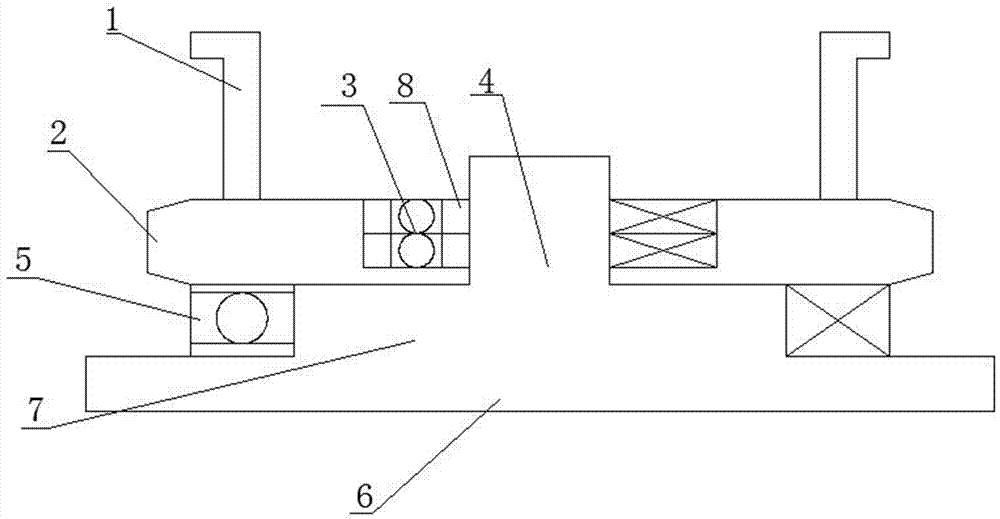
[0034] The invention proposes a circular knitting machine with a structure that revolves around the axis, which solves the shortcomings of poor radial and axial positioning accuracy when the tooth plate drives the needle cylinder in the prior art, and uses tapered roller bearings to adjust the radial and axial accuracy Control to effectively improve the radial and axial positioning accuracy of the needle cylinder during operation, such as figure 1 As shown, the following arrangement structure is adopted in particular: it includes a center column base, a shaft-circling bearing device and a tooth plate 2, the shaft-circling bearing device is nested on the center column base, and the tooth plate 2 is nested in the shaft-circling On the central bearing device, a bearing disc 8 is arranged on the bearing device around the shaft, and a tapered roller bearing 3 is arranged on the bearing disc 8 around the shaft.

[0035] When designing, the center column base is installed on the larg...

Embodiment 2

[0037]This embodiment is further optimized on the basis of the above-mentioned embodiments. Further, in order to better realize the present invention, the shaft-circling bearing device can be arranged on the center column base, and the shaft-circling bearing device can be mounted on the center column base. Make a circular horizontal rotation on the upper side, so that the main transmission teeth drive the crankshaft to transfer, such as figure 1 As shown, the following arrangement structure is adopted in particular: the center column base includes a center column 4, a column bearing plate 7 and a support platform 6, the central column 4 is arranged on the column bearing plate 7, and the column bearing plate 7 is arranged on On the support platform 6 , the 8 sets of bearing discs around the axis are set on the central column 4 .

[0038] When designing, the base of the center column is provided with a support platform 6, a column bearing plate 7 and a center column 4 in sequenc...

Embodiment 3

[0041] This embodiment is further optimized on the basis of any of the above-mentioned embodiments, further to better realize the present invention, so as to continue to carry the weight of the tooth plate; at the same time, reduce the wear between the large plate and the tooth plate and the load caused by wear increase, accuracy decreases, such as figure 1 As shown, the following arrangement structure is adopted in particular: a bearing carrying device is also arranged between the lower part of the crankset 2 and the support platform 6 .


PUM


Abstract

The invention discloses an axis-around operating structure of a circular weft knitting machine. The axis-around operating structure comprises a central column base, an axis-around bearing device and a crankset (2); the axis-around bearing device is arranged on the central column base in a nested mode, the crankset (2) is arranged on the axis-around bearing device in a nested mode, and an axis-around bearing carrying disc (8) is arranged on the axis-around bearing device and provided with conical roller bearings (3). The defect that in the prior art, the radial positioning precision and the axial positioning precision are poor when the crankset drives a needle cylinder to operate is overcome, the radial precision and the axial precision are controlled through the conical roller bearings, and therefore the radial positioning precision and the axial positioning precision which are achieved when the needle cylinder operates are improved.

Description

technical field [0001] The invention relates to the fields of knitting machinery technology, transmission technology and the like, specifically, it relates to a circular knitting machine rotating around an axis. Background technique [0002] Weft knitting is a method of weaving and producing textile fabrics. One or more yarns are introduced along the weft direction, and the knitting needles move up and down to weave to form loops, and are connected in series in the longitudinal direction to form a weft knitted fabric. Weft knitting circular weft machines are divided into three categories: single-sided, double-sided, and ribbed according to the type of weaving. [0003] In the transmission mechanism of the circular knitting machine, the motor drives the driving shaft gear through the transmission system, and the driving shaft gear is transmitted to the chainring gear, thereby driving the needle cylinder to carry the knitting needles and sinkers to run for weaving. The knitti...

Claims


Application Information

Patent Timeline
Patent Type & Authority Patents(China)
IPC IPC(8): D04B15/16
CPCD04B15/16
Inventor 陈涛杨祖凤陈祥平刘季平范小敏李琼秀张明勇陈健
Owner SICHUAN RES INST OF SILK SCI
Why Eureka
Try Eureka