Electric bypass valve

A bypass valve, electric technology, applied in wellbore/well components, earthwork drilling, flushing wellbore, etc., can solve the problems of increased drilling risk and cost, large mud loss, extended drilling cycle, etc., to achieve simple structure, Reduce the number of trips, convenience and reliability

Active Publication Date: 2017-02-22
CHINA PETROLEUM & CHEM CORP +1
View PDF5 Cites 4 Cited by
  • Summary
  • Abstract
  • Description
  • Claims
  • Application Information

AI Technical Summary

Problems solved by technology

When establishing a new rapid cycle, frequent tripping is often required, which causes the disadvantages of large mud loss and prolonged drilling cycle
At the same time, it also increases the risk and cost of drilling

Method used


Image

  • Electric bypass valve
  • Electric bypass valve

Examples


Embodiment Construction

[0023] The present invention will be further described below in conjunction with accompanying drawing.

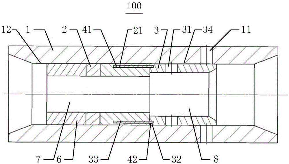
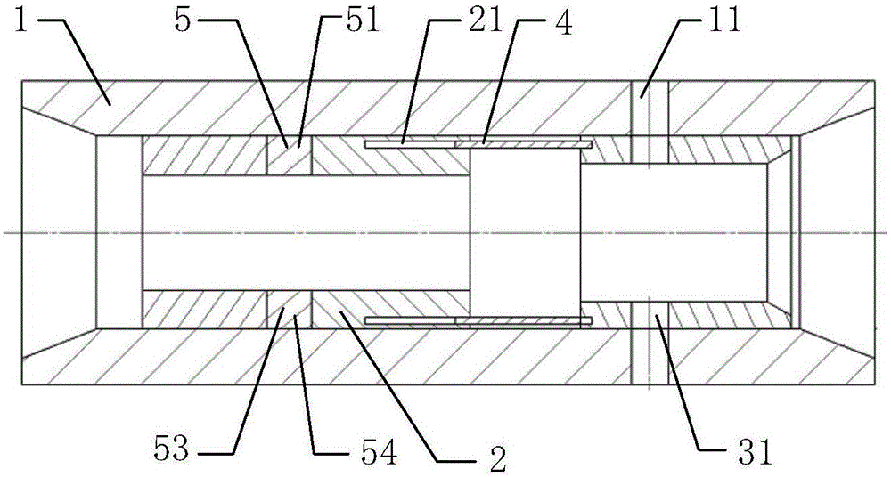
[0024] see figure 1 and figure 2 , which is a schematic diagram of the overall structure of the electric bypass valve according to the embodiment of the present invention. figure 1 It is schematically shown that the electric bypass valve 100 includes a valve body 1 , a driving motor 2 and a sliding sleeve 3 .

[0025] In the embodiment of the present application, the valve body 1 is approximately cylindrical and hollow inside. The valve body 1 needs to work underground for a long time, and the environment is relatively harsh, so the valve body 1 should have certain corrosion resistance and erosion resistance. In addition, since the valve body 1 needs to rotate along its own axial or circumferential direction downhole, the valve body 1 should also have certain properties of tensile and torsion resistance. Therefore, the valve body 1 should be made of corrosion-resistant...


PUM


Abstract

The invention relates to an electric bypass valve. The electric bypass valve comprises a valve body, a driving motor and a sliding sleeve. A plurality of first overflowing holes are formed in the circumferential direction of the valve body at intervals. The driving motor and the sliding sleeve are arranged in the valve body sequentially in a sleeved mode and are fixed connected in the circumferential direction. A plurality of second overflowing holes are formed in the circumferential direction of the sliding sleeve at intervals. When rotating according to the first direction, the driving motor drives the sliding sleeve to move in the axial direction of the valve body, and thus all the first overflowing holes communicate with the corresponding second overflowing holes. The electric bypass valve has the advantages that the electric bypass valve can be opened and closed at any moment according to actual needs so as to reduce the number of times of drill rising and falling.

Description

technical field [0001] The invention relates to the technical field of valve components used in oil, natural gas, shale gas and coal bed methane, in particular to an electric bypass valve. Background technique [0002] During the drilling of oil, natural gas, shale gas and coalbed methane, when complex situations are encountered downhole, such as plugging of drill bit water holes, damage of downhole power drilling tools and plugging operations, rapid circulation is temporarily required. When establishing a new rapid cycle, frequent tripping is often required, which causes the disadvantages of large mud loss and prolonged drilling cycle. At the same time, it also increases the risk and cost of drilling. [0003] Based on the analysis of the existing technology, it is necessary to design an electric bypass valve. When the rapid circulation is required, the bypass valve is opened. When the rapid circulation is over, the bypass valve is closed and drilling is continued to reduc...

Claims


Application Information

Patent Timeline
Patent Type & Authority Applications(China)
IPC IPC(8): E21B21/10
Inventor 马东军刘鹏范红康孙明光陶兴华郭瑞昌王果胡越发刘建华刘卫东张建龙周号博王立双
Owner CHINA PETROLEUM & CHEM CORP
Why Eureka
Try Eureka