Radial azimuth stepless angle adjustment mechanism for gas drilling manifold

A technology of gas drilling and azimuth, which is applied in liquid/gas jet drilling, earthwork drilling, wellbore flushing, etc. It can solve the problems of high work intensity and working time, and adjust the angle and direction of pipelines at will, so as to shorten the installation time. The effect of shortening the operation cycle, reducing the installation work time, and saving the installation cost

Active Publication Date: 2019-05-10
CHINA NAT PETROLEUM CORP CHUANQING DRILLING ENG CO LTD
View PDF6 Cites 12 Cited by
  • Summary
  • Abstract
  • Description
  • Claims
  • Application Information

AI Technical Summary

Problems solved by technology

However, the pipeline described in this invention is still a traditional pipeline, and the angle and direction of the pipeline cannot be adjusted at will during the installation process. It is still a tentative connection method, often repeatedly installed and disassembled, and the work intensity and working time are very high.

Method used


Image

  • Radial azimuth stepless angle adjustment mechanism for gas drilling manifold
  • Radial azimuth stepless angle adjustment mechanism for gas drilling manifold
  • Radial azimuth stepless angle adjustment mechanism for gas drilling manifold

Examples


Embodiment 1

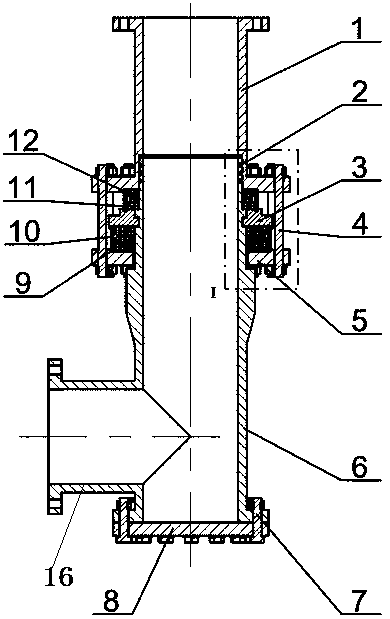
[0035] A radial azimuth stepless angle adjustment mechanism for a gas drilling manifold, including a fixed nipple 1, a clamping piece, a screw set 4, a suspension flange 5, and a rotating nipple 6, and the upper end of the rotating nipple 6 is connected to the fixed nipple 1 is plugged and sealed, and the lower end is provided with a prefabricated fixed-angle outlet connection end 16. The suspension flange 5 is set on the swivel joint 6, and the clamping part is located between the lower end surface of the fixed joint 1 and the suspension flange 5. The rotating short joint 6 is suspended on the clamping part, and the lower end of the hanging flange 5 and the fixed short joint 1 is fixedly connected through the screw kit 4. The annular space between the clamping part and the hanging flange 5 is provided with a roller bearing, and the clamping A roller bearing is arranged between the part and the lower end surface of the fixed pup joint 1.

[0036] In this embodiment, the clampi...

Embodiment 2

[0049] This embodiment further illustrates the present invention in conjunction with the accompanying drawings. The invention can be used in gas drilling techniques such as dry gas drilling (air, nitrogen), atomization drilling, foam drilling and aeration drilling, and manifold systems in other fields.

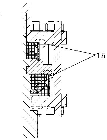
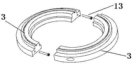
[0050] The present invention includes fixed short joint 1, "O" type sealing ring 2, semicircle clamp 3, long screw kit 4, suspension flange 5, rotating short joint 6, flange bolt kit 7, blind plate 8, thrust self-aligning roller Bearing 9, dustproof nylon ring a10, dustproof nylon ring b11, thrust cylindrical roller bearing 12. The long screw kit 4 includes a screw, a nut, and a spring washer. Flange bolt kits include bolts, nuts, spring washers.

[0051] The fixed nipple 1 is fixed on the upstream sand discharge pipeline. The rotating sub-joint 6 and the fixed sub-joint 1 belong to the plug-in relationship, and the two realize radial sealing through three "O"-shaped sealin...


PUM


Abstract

The invention discloses a radial azimuth stepless adjustment for a gas drilling manifold, comprising a fixing sub, a fastener, a hanging flange and a rotating sub; the upper end of the rotating sub is in insertion connection and hermetic fit with the fixing sub, the lower end of the rotating sub is provided with an outlet connection end having predetermined fixing angle, the hanging flange sleeves the rotating sub, the fastener is positioned between the lower end of the fixing sub and the hanging flange, the rotating sub is hung to the fastener, the hanging flange is fixedly connected to the lower end of the fixing sub through a screw set, a roller bearing is disposed in an annular space between the fastener and the hanging flange, and a roller bearing is disposed between the fastener and the lower end of the fixing sub. The radial azimuth stepless adjustment enables the direction of a sand discharge line to be adjusted and enables the sand discharge line to be quickly connected out of a well site, repeated mounting and demounting is avoided, workload and work intensity are greatly reduced for workers, mounting period is shortened, worker cost and crane application expenditure are reduced.

Description

technical field [0001] The invention relates to a gas drilling manifold, in particular to a radial azimuth stepless angle adjustment mechanism for a gas drilling manifold, belonging to the technical field of oil and gas drilling (drilling) engineering. Background technique [0002] Gas drilling is a drilling method that uses gas as a circulation and sand-carrying medium. Compared with conventional drilling fluid drilling, the bottom hole pressure of gas drilling is much lower than the bottom hole fluid column pressure, and the negative pressure is always maintained during the drilling process. Underbalanced drilling. As a new technology developed and matured in China in the 1980s, gas drilling has formed four main technologies of dry gas drilling (air, nitrogen), atomization drilling, foam drilling and air-filled drilling, which have the advantages of improving mechanical penetration rate and controlling malignant Lost circulation, discovery and protection of reservoirs and...

Claims


Application Information

Patent Timeline
Patent Type & Authority Patents(China)
IPC IPC(8): E21B21/16E21B21/02E21B7/18
CPCE21B7/18E21B21/02E21B21/085E21B21/16
Inventor 范黎明刘殿琛韩烈祥董仕明邓柯李宬晓吴俊先羿
Owner CHINA NAT PETROLEUM CORP CHUANQING DRILLING ENG CO LTD
Why Eureka
Try Eureka