
Oil cooling device and air conditioner device with oil cooling device

A technology of cooling oil and being cooled, applied in mechanical equipment, liquid variable capacity machinery, variable capacity pump components, etc., can solve the problems of uneven oil temperature distribution, large fluctuations in the control process, mixing of refrigerants, etc., to improve cooling area, improve the cooling effect, prevent the effect of low cooling

Active Publication Date: 2017-02-22
GREE ELECTRIC APPLIANCES INC
View PDF7 Cites 0 Cited by
  • Summary
  • Abstract
  • Description
  • Claims
  • Application Information

AI Technical Summary

Problems solved by technology

[0004] However, the cost of using an external oil cooler to cool the oil is high, foreign matter such as iron filings in the lubricating oil is easy to block the external oil cooler, and at the same time, the oil temperature is prone to cooling too low.
Using the way of injecting cold oil will lead to uneven distribution of oil temperature, resulting in local oil temperature being too low and local oil temperature being too high, and the oil temperature cannot be accurately measured. When the controlled oil temperature reaches the target value, the actual oil temperature is higher than the demand. If the oil temperature is low, the cold oil control valve must be closed, resulting in repeated control, large fluctuations in the control process, and long stabilization time
If the oil temperature is too low, a large amount of refrigerant will be mixed into the lubricating oil. At the same time, the viscosity of the lubricating oil will increase, and the power consumption of the bearing will increase.

Method used


Image

  • Oil cooling device and air conditioner device with oil cooling device
  • Oil cooling device and air conditioner device with oil cooling device
  • Oil cooling device and air conditioner device with oil cooling device

Examples


Embodiment Construction

[0031] The present invention will be described in detail below with reference to the accompanying drawings and examples.

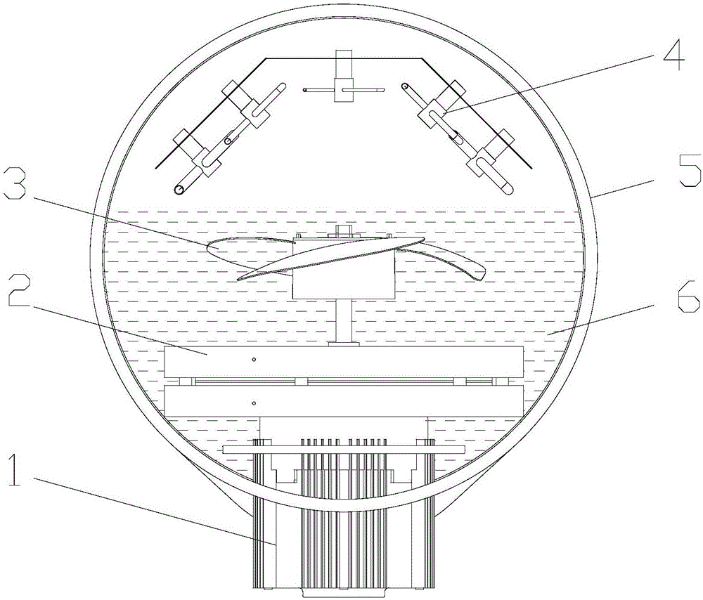
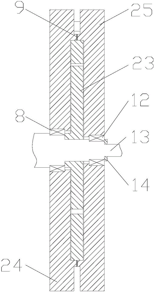
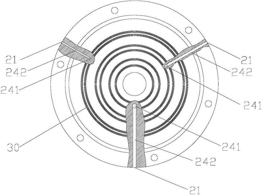
[0032] Such as figure 1 As shown, according to the embodiment of the present invention, the cooling oil device includes a pulse distribution part 2 and a spray part 4, and the pulse distribution part 2 includes a medium inlet 21 for introducing a cooling medium, a medium outlet 22 for delivering a cooling medium to the spray part 4 and The flow distribution structure 23 that controls the communication between the medium inlet 21 and the corresponding medium outlet 22 or blocks, and the medium outlet 22 is connected with the spray part 4 .

[0033] The cooling oil device sends the cooling medium to the spraying part 4 through the pulse distribution part 2, and sprays the cooling medium to the lubricating oil to be cooled through the spraying part 4 to realize the temperature control of the lubricating oil. The distribution structure 23 of the pulse distrib...


PUM

PropertyMeasurementUnit
Central angleaaaaaaaaaa

Abstract

The invention provides an oil cooling device and an air conditioner device with the oil cooling device. The oil cooling device comprises a pulse flow distributing part and a spraying part. The pulse flow distributing part comprises a medium inlet leading a cooling medium in, a medium outlet conveying the cooling medium to the spraying part, and a flow distributing structure controlling the medium inlet and the corresponding medium outlet to be connected or disconnected, and the medium outlet is connected with the spraying part. Through the oil cooling device, the continuous cooling medium flow is converted into the pulse cooling medium flow, accordingly control over the cooling amount is achieved, and the cooling oil temperature is reliably controlled while the lubricating oil is cooled.

Description

technical field [0001] The invention relates to the field of air conditioning equipment, in particular to an oil cooling device and an air conditioning equipment with the same. Background technique [0002] When the centrifugal compressor is working, a lot of heat will be generated due to the working of the bearings and gears. If it is not cooled in time, the excessive heat will affect the bearing performance of the centrifugal compressor. Moreover, if the oil temperature is too high, the viscosity of the lubricating oil will decrease, and the stiffness of the oil film will decrease, resulting in bearing wear. For this reason, it is necessary to control the lubricating oil temperature and cool the lubricating oil. [0003] In order to solve the lubricating oil cooling problem, most of the fixed-frequency centrifugal compressors in the prior art use the lubricating oil in the oil tank to be cooled by an external oil cooler (plate heat exchanger) to cool the oil temperature ...

Claims


Application Information

Patent Timeline
IPC IPC(8): F04B39/06F04B39/08F04B39/02
CPCF04B39/0269F04B39/062F04B39/08
Inventor 刘魏周堂张治平李宏波周宇张永斌尹威华
Owner GREE ELECTRIC APPLIANCES INC
Learn More