
Massage bathtub pump

A bathtub and pump cover technology, which is applied to pumps, pump devices, pump components, etc., can solve the problems of jacuzzi pumps, such as high vibration and noise, poor sealing effect, and fast wear, to achieve extended working life, convenient operation, and reduced noise effect

Active Publication Date: 2017-02-22
GUANGDONG LINGXIAO PUMP IND
View PDF6 Cites 1 Cited by
  • Summary
  • Abstract
  • Description
  • Claims
  • Application Information

AI Technical Summary

Problems solved by technology

[0003] In order to solve the technical defects of the massage bathtub pump in the prior art, such as large vibration and noise, poor sealing effect, fast wear, high loss and short life, the invention proposes a massage bathtub pump

Method used


Image

  • Massage bathtub pump
  • Massage bathtub pump
  • Massage bathtub pump

Examples


Embodiment 1

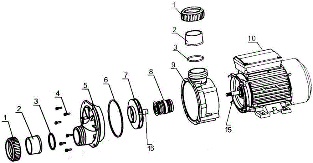
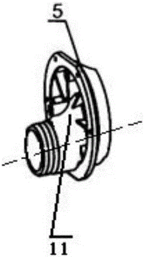
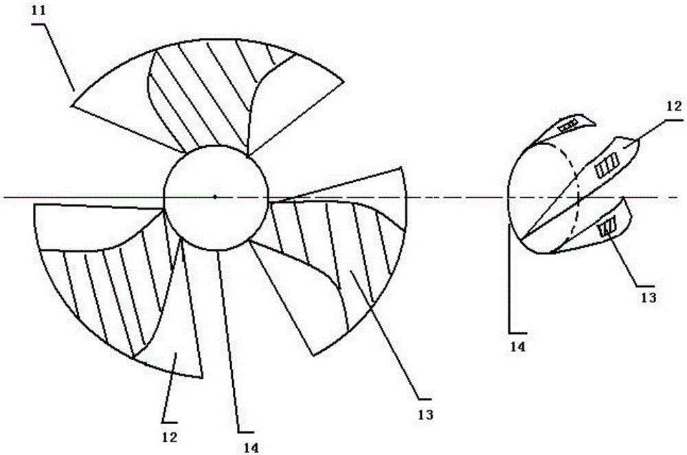
[0022] A massage bathtub pump, comprising a pump casing assembly 9, an impeller 7, a bearing 15, a pump cover assembly 5 and a motor 10, the impeller 7 is sleeved on the bearing 15 through a shaft sleeve 16, and one side of the impeller 7 passes through The large O-ring 6 is in sealing connection with the pump cover assembly 5, and the other side is connected with the pump casing assembly 9 through a mechanical seal 8, and the shaft sleeve 16 passes through the mechanical seal 8 and is socketed with the bearing 15, and the pump cover The assembly 5 is composed of a suction section, a cover shell and an introduction part 11. The introduction part 11 is composed of three guide vanes 12 connected by a circular collar 14 and bent in a certain direction. The three guide vanes 12 are uniform Distributed around the circle of the circular collar 14, the guide vanes 12 are fan-shaped, and the three guide vanes 12 are covered on the diverging suction pipe of the suction section. Protrud...

Embodiment 2

[0024] A massage bathtub pump, comprising a pump casing assembly 9, an impeller 7, a bearing 15, a pump cover assembly 5 and a motor 10, the impeller 7 is sleeved on the bearing 15 through a shaft sleeve 16, and one side of the impeller 7 passes through The large O-ring 6 is in sealing connection with the pump cover assembly 5, and the other side is connected with the pump casing assembly 9 through a mechanical seal 8, and the shaft sleeve 16 passes through the mechanical seal 8 and is socketed with the bearing 15, and the pump cover The assembly 5 is composed of a suction section, a cover shell and an introduction part 11. The introduction part 11 is composed of three guide vanes 12 connected by a circular collar 14 and bent in a certain direction. The three guide vanes 12 are uniform Distributed around the circle of the circular collar 14, the guide vanes 12 are fan-shaped, and the three guide vanes 12 are covered on the diverging suction pipe of the suction section. Protrud...


PUM


Abstract

The invention provides a massage bathtub pump which comprises a pump shell assembly, an impeller, a bearing, a pump cover assembly and an electric motor, wherein the impeller sleeves the bearing by a shaft sleeve; one side of the impeller is in a sealed connection with the pump cover assembly by a large O-shaped ring, and the other side is connected to the pump shell assembly through mechanical sealing; the shaft sleeve passes through the mechanical sealing and is in a sleeved connection with the bearing; the pump cover assembly is composed of a suction section, a cover shell and a lead-in component; the lead-in component is composed of three guide blades which are connected by round sleeve rings and bent in a certain direction; the guide blades are shaped like sectorial rings; the three guide blades cover a gradually expanded suction pipe of the suction section; and a raised guide block is disposed on each guide blade. The massage bathtub pump is characterized in that flow guide sheets are installed, so that water flows can enter the pump body smoothly; water flow pressure is reduced; collision of the water flows to the pump cover is reduced; efficiency is increased, and noise is reduced; local wear is avoided; a pump performance scope is expanded; and operations are convenient.

Description

technical field [0001] The invention relates to the technical field of pump bodies, in particular to a massage bathtub pump. Background technique [0002] The massage bathtub pump is a specific functional pump widely used in the massage field. The motor used in the existing massage bathtub pump is a high-speed series motor. When the motor is running, it will generate relatively large vibration under high speed operation. and noise, while the motor is directly connected to the shell through the rubber pad, the shell and the rubber pad cannot prevent the vibration and noise of the motor well; when the air pump is installed on the bathtub, the vibration and noise will directly affect the quietness of the user ,comfortable environment. Several massage bathtubs and bath pumps are disclosed in the prior art. For example, CN2873184Y discloses a massage bathtub, which includes a cylinder body forming a water storage space inside, and one or more water jet massage nozzles are arrang...

Claims


Application Information

Patent Timeline
Patent Type & Authority Applications(China)
IPC IPC(8): F04D13/06F04D29/08F04D29/44F04D29/66
CPCF04D13/06F04D29/086F04D29/445F04D29/669
Inventor 李光勇范河生
Owner GUANGDONG LINGXIAO PUMP IND
Learn More