
Permeation pipe sealing device

A sealing device and permeation pipe technology, applied in the direction of pipe elements, pipes/pipe joints/pipe fittings, mechanical equipment, etc., to achieve the effect of reducing cracking phenomenon, reducing cracking and strong application

Inactive Publication Date: 2017-02-22
BEIJING CHANGCHENG INST OF METROLOGY & MEASUREMENT AVIATION IND CORP OF CHINA
View PDF8 Cites 0 Cited by
  • Summary
  • Abstract
  • Description
  • Claims
  • Application Information

AI Technical Summary

Problems solved by technology

[0005] The purpose of the present invention is to solve the problem that the permeation tube does not leak the permeation medium under high pressure, and propose a permeation tube sealing device, which can be used in standard humidity gas generating instruments

Method used


Image

  • Permeation pipe sealing device
  • Permeation pipe sealing device
  • Permeation pipe sealing device

Examples


Embodiment 1

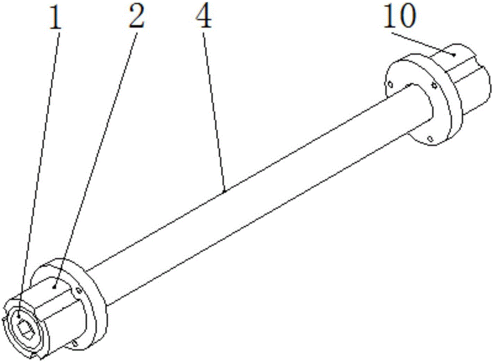
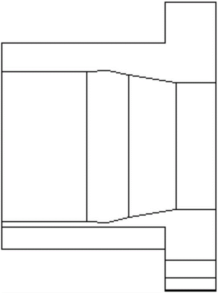
[0031] The utility model relates to a permeation tube sealing device, which is suitable for working in a furnace cavity with a small diameter. The device includes a permeation tube 4 , a first plug 1 , a second plug 9 , a first inner casing 2 and a second inner casing 10 . like figure 1 shown.

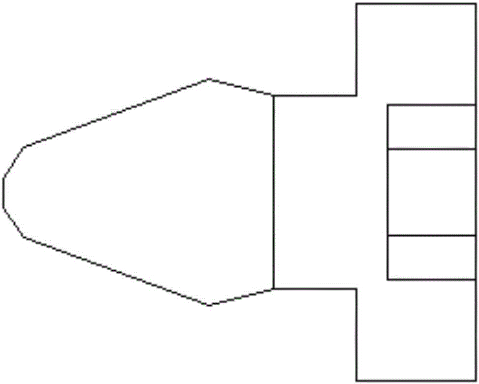
[0032] The outer surface of the tail of the first plug 1 is provided with threads, the middle part is a cone, and the head is a spherical cone-shaped structure. Wherein, the vertebral body structure in the middle part is specifically a structure that first expands and then shrinks from the vertebral bottom to the vertebral head. like figure 2 shown.

[0033] The middle position of the tail of the first plug 1 is provided with a notch 12. The shape of the notch 12 is cross-shaped, so that the Phillips screwdriver can be inserted into the notch 12 to further rotate the first plug 1, so that the threads on the outer surface of the tail of the first plug 1 The threads on the inner su...

Embodiment 2

[0045] The utility model relates to a permeation tube sealing device, which is suitable for large-diameter furnace chambers. The device comprises a permeation tube 4, a first plug 1, a second plug 9, a first inner casing 2, a second inner casing 10, a first outer casing 3, a second outer casing 11, a bracket 5, a first Support bar 6, second support bar 7, third support bar 8. like image 3 , Figure 4 shown.

[0046] The outer surface of the tail of the first plug 1 is provided with threads, the middle part is a cone, and the head is a spherical cone-shaped structure. Wherein, the vertebral body structure in the middle part is specifically a structure that first expands and then shrinks from the vertebral bottom to the vertebral head. The middle position of the tail of the first plug 1 is provided with a notch 12, and the shape of the notch 12 is hexagonal, so that a hexagonal screwdriver can be inserted into the notch 12 to further rotate the first plug 1, so that the thr...


PUM


Abstract

The invention relates to a permeation pipe sealing device, and belongs to the technical field of permeation method humidity generators. A plug structure is improved; a plug with the head part as a spherical surface structure and the middle part as a cone shrinking after expanding is adopted to press with a permeation pipe; and an inner sleeve tight sealing mode is matched to realize no pollution of a permeation medium and no leakage of the permeation medium in high-pressure state. In addition, through a mode of arranging a bracket and an outer sleeve on the permeation pipe, the wall collision phenomenon of putting the permeation pipe in a constant-temperature cavity is further effectively prevented, and the permeation pipe is suitable for cavities with different sizes. The device is suitable for permeation pipes with different structures, sizes and permeation rates, and has such advantages as high adaptability and high reliability.

Description

technical field [0001] The invention belongs to the technical field of osmotic humidity generators, and relates to a sealing device for a osmotic tube. Background technique [0002] The permeation tube is mainly used in the osmosis humidity generator. The permeation tube is placed in a constant temperature chamber through the permeability of the permeated medium under a certain sealing material and a certain temperature condition, combined with the gas flow rate to obtain the specified dew point gas. used in . In the traditional sense, the sealing of the permeation tube usually adopts heat sealing, and the two ends of the permeation tube are sealed by heat-treating the two ends of the permeation tube with an alcohol lamp to melt and then bonded at high temperature. This method is due to the heating temperature and the permeation tube Influenced by the thickness of the pipe diameter and the flatness of the flat-nose pliers used, the sealed permeation pipe will crack under hi...

Claims


Application Information

Patent Timeline
Patent Type & Authority Applications(China)
IPC IPC(8): F16L55/115
CPCF16L55/115
Inventor 吕国义张贺周庆福杨新圆
Owner BEIJING CHANGCHENG INST OF METROLOGY & MEASUREMENT AVIATION IND CORP OF CHINA
Learn More