A fluorescent tube for slim pipe diameter

A technology for fluorescent tubes and tubes, applied in the field of fluorescent tubes, which can solve the problems of reducing the amount of electronic powder coating, affecting the pumping speed, and reducing the distance, so as to avoid the phenomenon of filament bumping into walls, improve the production pass rate, and ensure coating volume effect

Inactive Publication Date: 2008-08-06
ZHEJIANG YANKON GROUP
View PDF0 Cites 0 Cited by
  • Summary
  • Abstract
  • Description
  • Claims
  • Application Information

AI Technical Summary

Problems solved by technology

However, this solution first requires the production of a suitable small core column, and the production of this small core column is quite difficult in terms of technology, because the actual diameter of the glass tube with a diameter below φ6mm after removing the thickness of the tube wall is φ4.5mm Below, this means that the horn pipe diameter of the core column is less than φ4mm, and the outer diameter of the exhaust stem of the manufactured core column must be less than φ1.8mm to match such a horn, and the actual diameter of the exhaust stem is only less than φ0.9mm, while It is very difficult to manufacture such a small-diameter exhaust stem, which will obviously affect the pass rate of production, not to mention that the smaller the diameter of the glass tube, the smaller the diameter of the exhaust stem is required, and when the actual aperture of the exhaust stem When it is below 0.9mm, it will also affect the pumping speed when exhausting (especially on automatic exhaust equipment), thereby affecting the vacuum degree in the lamp tube, and ultimately having a negative impact on product quality; on the other hand, shortening the filament The overall length will reduce the distance between the two guide wires connecting the two ends of the filament, thereby reducing the coating amount of electronic powder, and the reduction in the amount of electronic powder will significantly reduce the life of the fluorescent tube

Method used


Image

  • A fluorescent tube for slim pipe diameter

Examples


Embodiment 1

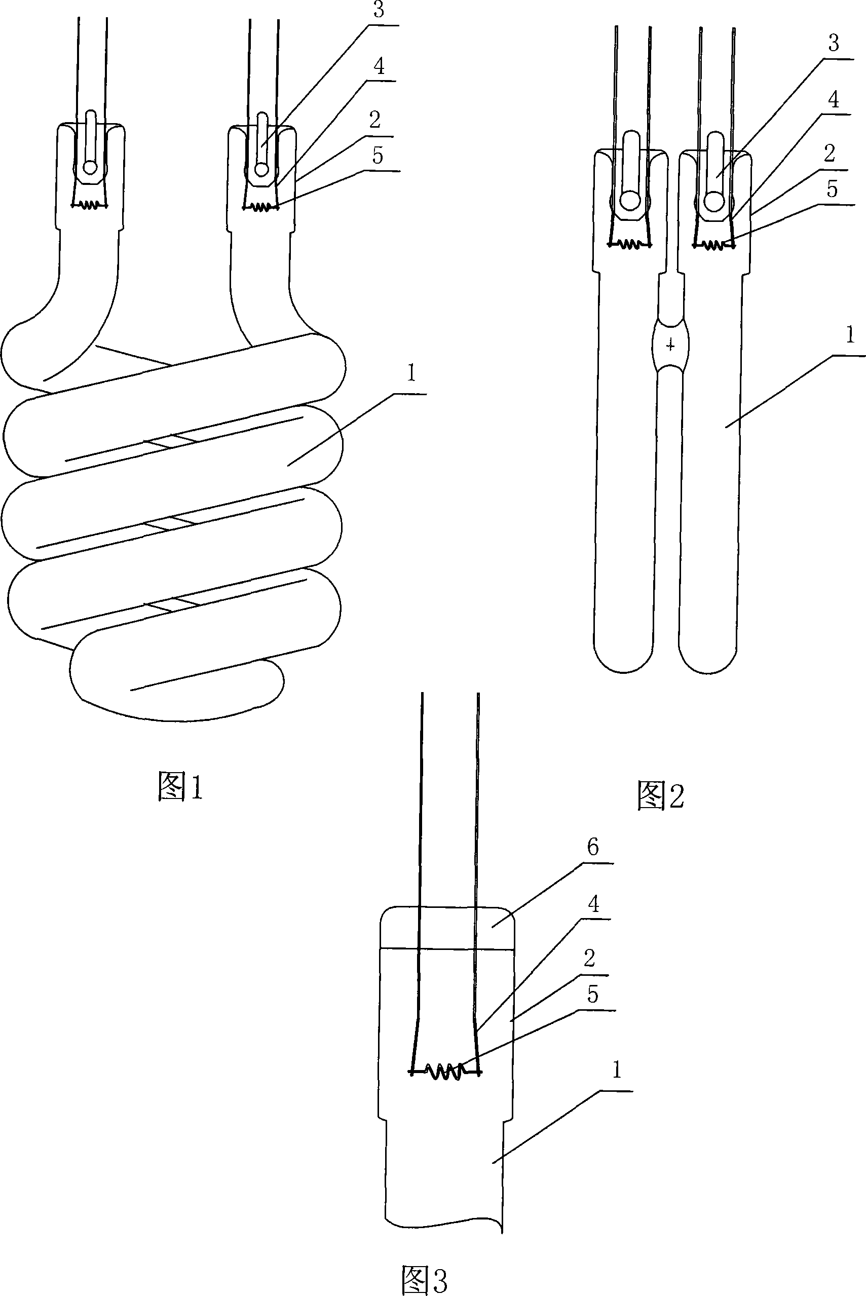
[0015] Embodiment 1: As shown in Figure 1, a fluorescent tube with a small diameter includes a main tube 1, the end of the main tube 1 is fused with an auxiliary tube 2, the main tube 1 is a spiral glass tube, The diameter of the main lamp tube 1 is Φ4mm, the diameter of the auxiliary lamp tube 2 is Φ7mm, the end of the auxiliary lamp tube 2 is sealed and fixed with a stem 3, the stem 3 is provided with a guide wire 4 and a filament 5, and the filament 5 is set In the auxiliary lamp tube 2.

Embodiment 2

[0016] Embodiment two: as shown in Figure 2, other structures are the same as embodiment one, the difference is that the main body lamp tube 1 is a U-shaped glass tube, the tube diameter of the main body tube 1 is Φ5mm, and the tube diameter of the auxiliary lamp tube 2 is Φ9mm.

Embodiment 3

[0017] Embodiment 3: As shown in Figure 3, other structures are the same as Embodiment 1 or Embodiment 2, the difference is that the diameter of the main lamp tube 1 is Φ6mm, the diameter of the auxiliary lamp tube 2 is Φ8mm, and no stem is used Instead, the end of the auxiliary lamp tube 2 is fused and pinched to form a pinch portion 6 , and the guide wire 4 connected to the filament 5 is fixed on the pinch portion 6 .

[0018] In the above embodiments, the main lamp tube 1 can also be replaced by other glass tubes of various shapes.


PUM


Abstract

The invention discloses a fluorescent pipe with a thin pipe diameter, comprising a main body luminous pipe and a filament component, wherein the filament component comprises a filament; the fluorescent pipe is characterized in that an end part of the main body luminous pipe is connected with an auxiliary luminous pipe, the diameter of which is larger than that of the main body luminous pipe; the filament component is fixedly connected with the end part of the auxiliary luminous pipe; the filament is arranged inside the auxiliary luminous pipe; the fluorescent pipe has the advantages that the auxiliary luminous pipe which is relatively larger in diameter is sealed, the total length of the filament is not affected by the thinning main body luminous pipe, the phenomenon of the filament contacting the wall can be effectively avoided without shortening the total length of the filament, the coating quantity of electric powders are guaranteed, the service life of the fluorescent lamp is effectively improved and the production yield of the fluorescent pipe can also be improved along with the reduction of the phenomenon of the filament contacting the wall.

Description

technical field [0001] The invention relates to a fluorescent lamp, in particular to a fluorescent lamp with a small diameter. Background technique [0002] Existing fluorescent tubes are provided with filament assemblies such as stems and the like at their two ends, but for fluorescent tubes with small diameters, especially energy-saving lamps with a diameter below φ6mm, due to the small diameter ( Excluding the thickness of the tube wall (the actual aperture is below 4.5mm), there is a phenomenon that the filament is easy to touch the lamp tube wall when making the seal. When the filament touches the wall of the lamp tube, there is a great potential safety hazard in the fluorescent lamp. When the life of the fluorescent lamp ends, the contact between the filament and the wall of the lamp tube is likely to melt or burn through. In addition, when the filament hits the wall of the lamp tube, the electronic powder of the filament will be sputtered onto the wall of the lamp tu...

Claims


Application Information

Patent Timeline
Patent Type & Authority Applications(China)
IPC IPC(8): H01J61/00H01J61/30H01J61/36
Inventor 茅建龙
Owner ZHEJIANG YANKON GROUP
Why Eureka
Try Eureka