Air-cooling unit steam turbine waste heat utilization system

A technology for air-cooled units and steam turbines, applied in lighting and heating equipment, combustion methods, indirect carbon dioxide emission reduction, etc., can solve problems such as corrosion, increase energy consumption of units, and low-grade energy for waste heat utilization, and achieve the effect of preventing low-temperature corrosion.

Active Publication Date: 2019-01-11
中国大唐集团科学技术研究总院有限公司
View PDF4 Cites 0 Cited by
  • Summary
  • Abstract
  • Description
  • Claims
  • Application Information

AI Technical Summary

Problems solved by technology

Due to the current technical measures such as low-temperature economizer, due to the influence of low-temperature corrosion and other factors on the exhaust gas temperature, the energy grade of waste heat utilization is low, and the space for improving unit efficiency is limited.
[0005] In addition, in order to prevent low-temperature corrosion at the cold end of the space preheater in winter, steam extraction or auxiliary steam heating type heaters are usually used, the system is complex, and the energy consumption of the unit is increased due to the consumption of steam extraction

Method used


Image

  • Air-cooling unit steam turbine waste heat utilization system
  • Air-cooling unit steam turbine waste heat utilization system

Examples


Embodiment 1

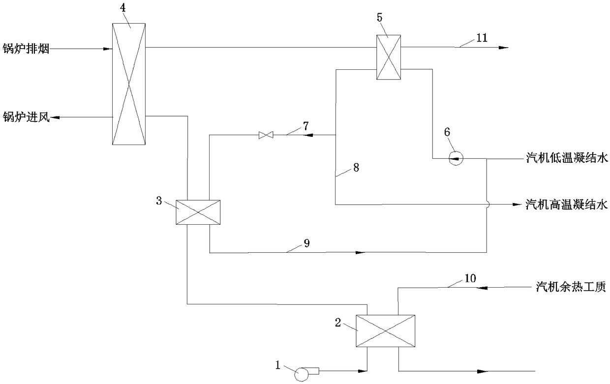
[0025] as attached figure 1 As shown, the steam turbine waste heat utilization system of the air-cooled unit in this embodiment includes a cold air preheater 2 and a heater 3 installed on the air duct between the boiler cold air fan 1 and the air side inlet of the air preheater 4, and installed on the air preheater 4. The smoke-water heat exchanger 5 between the flue gas side outlet and the dust remover flue 11 is connected to the steam turbine waste heat working medium pipeline 10 of the cold air preheater 2, connected to the smoke-water heat exchanger 5, and the condensate booster pump 6. The condensed water pipeline 7 of the inlet heater is connected to the water side inlet of the heater 3, and the condensed water pipeline 9 of the outlet heater is connected to the water side outlet of the heater 3; the water side outlet of the smoke-water heat exchanger 5 is connected to the heater The condensed water pipeline 7 of the fan is connected with the condensed water pipeline 8 a...

Embodiment 2

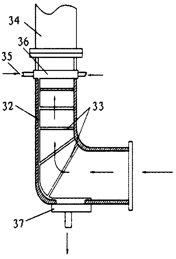
[0028] Such as figure 2 As shown, in this embodiment, the steam turbine waste heat utilization system of the air-cooled unit in this embodiment, on the basis of Embodiment 1, the air heater is located below the inlet air duct 34 of the air preheater, and the outlet air duct of the air heater 3 is connected to the The inlet duct 34 of the air preheater is vertically connected, the membrane heat dissipation pipe row 32 is installed on the air duct wall of the air heater, the fin heat dissipation pipe 33 is installed in the air passage of the air heater, the membrane type heat dissipation pipe row 32 and the fin The air inlet of the fin radiating pipe 33 is communicated with the heater air source 35 through a pipeline.

[0029] In order to make full use of boiler waste heat, a heat source inlet header 36 is installed on the upper part of the heater, and a heat source outlet header 37 is installed on the lower part of the heater. The boiler waste heat pipeline is connected to the...

Embodiment 3

[0032] as attached figure 1 As shown, the method for utilizing the waste heat of the steam turbine of the system air-cooling unit described in Embodiment 1 is:

[0033] The waste heat working medium in the steam turbine waste heat working medium pipeline 10 enters the cold air preheater 2 to heat the boiler cold air and then returns to the turbine side; the boiler cold air passes through the air heater 3 and is reheated by the condensate water from the condensate water pipeline 7, and then enters the air preheater 4 to be discharged Boiler flue exhaust heat, this part of waste heat enters the flue water heat exchanger 5 with the flue gas to heat the low-temperature condensate water of the turbine, and the heated high-temperature condensate part returns to the condensate water system on the turbine side through the condensate water pipeline 8.

[0034]Since the waste heat of the steam turbine is used to heat the cold air of the boiler, the flue gas temperature at the outlet of ...


PUM


Abstract

The invention relates to an air cooling unit steam turbine waste heat using system and method. The system is characterized in that a waste heat working medium in a steam turbine waste heat working medium pipe returns to the steam turbine side after entering a cold air pre-heater (2) to heat boiler cold air; the boiler cold air passes through an air heater to be subject to water condensation through a condensation water pipe (7), is heated again, and then enters an air pre-heater to push out boiler discharge smoke waste heat; and the part of waste heat enters a smoke-water heat exchanger along with smoke to be used for heating steam turbine low temperature condensation water, and a part of heated high temperature condensation water returns to a steam turbine side condensation water system through a condensation water pipe. As the steam turbine waste heat is used for heating the boiler cold air, the outlet smoke temperature of the air pre-heater is improved; and the smoke water heat passes through a smoke-water heat exchanger (5) to be absorbed by the low temperature condensation water, the low temperature condensation water becomes the high temperature condensation water to return to the steam turbine side so as to be used for pushing a high temperature section to carry out steam extraction and acting, and therefore the overall circulation heat efficiency of a unit is improved.

Description

technical field [0001] The invention relates to the technical field of thermal power generation, in particular to a steam turbine waste heat utilization system of an air-cooling unit. Background technique [0002] Most places in northern my country, especially the Three North regions, are relatively water-scarce areas. In the construction of thermal power units in places where the drought index exceeds the standard, air cooling is usually required to achieve the purpose of saving water. However, when the unit is air-cooled, the cooling effect is far worse than that of the wet cooling method, resulting in high back pressure of the steam turbine, which affects the power generation efficiency of the unit, and even cannot run at full load during peak load in summer, and is more sensitive to ambient temperature changes. [0003] Regardless of whether it is an air-cooled steam turbine or a wet-cooled steam turbine, based on the steam Rankine power cycle theory, the exhaust steam ...

Claims


Application Information

Patent Timeline
Patent Type & Authority Patents(China)
IPC IPC(8): F23L15/00
CPCF23L15/00Y02E20/34
Inventor 张振华孙英博刘岩宋寅邢洪涛万逵芳赵文波王虎郭婷婷张志刚吴智泉
Owner 中国大唐集团科学技术研究总院有限公司
Why Eureka
Try Eureka