
Novel heat exchanger core

A heat exchanger and core technology, applied in heat exchange equipment, lighting and heating equipment, damage protection, etc., can solve the problems of reduced service life of heat exchanger, uneven cleanliness, fouling, etc. Avoid mixed flow between fluids, good heat exchange effect

Active Publication Date: 2017-02-22
AEROSPACE HIWING HARBIN TITANIUM IND
View PDF7 Cites 1 Cited by
  • Summary
  • Abstract
  • Description
  • Claims
  • Application Information

AI Technical Summary

Problems solved by technology

Due to the narrowness of the microchannel pipes, the cleanliness of the fluid working medium is high. At present, the cleanliness of the fluid working medium used in the heat exchanger is different. When the cleanliness of the working medium is not high, it often occurs Scale, or the diameter of particles in the working fluid is too large and blocked, which reduces the service life of the heat exchanger

Method used


Image

  • Novel heat exchanger core
  • Novel heat exchanger core
  • Novel heat exchanger core

Examples


Embodiment 1

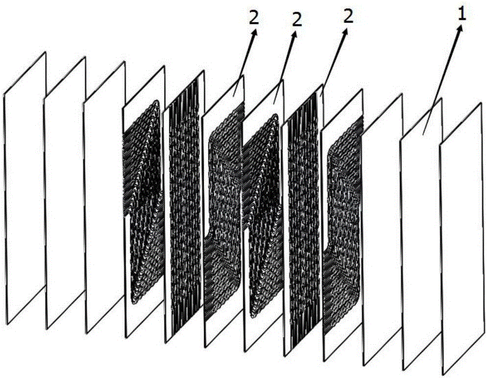
[0035] Combine Figure 1-4 , This embodiment provides a new type of heat exchanger core,

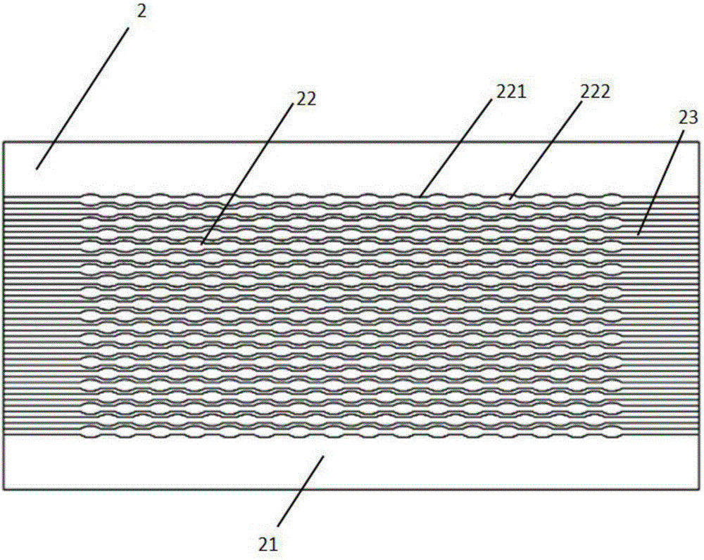
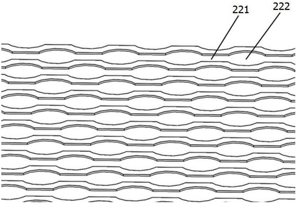
[0036] Including cover plate 1, first heat exchange plate group, second heat exchange plate group, and third heat exchange plate group, among which the first heat exchange plate group, the second heat exchange plate group, and the third heat exchange plate group The plate groups are stacked alternately, and the cover plate 1 is stacked on the outside of the heat exchange plate group. The first heat exchange plate group carries the first heat exchange fluid, and the second heat exchange plate group carries the second heat exchange fluid. , The third heat exchange plate group carries the third heat exchange fluid; each heat exchange plate group includes a heat exchange plate 2; the heat exchange plate 2 is processed from the base 21 and chemically etched on the base The two ends of the heat exchange runner are located on the side of the substrate, and are the inlet and outlet of the heat exc...

Embodiment 2

[0038] Including cover plate 1, first heat exchange plate group, second heat exchange plate group, third heat exchange plate group, fourth heat exchange plate group, of which the first heat exchange plate group and the second heat exchange plate group The plate group, the third heat exchange plate group, and the fourth heat exchange plate group are alternately stacked, the cover plate 1 is stacked on the outside of the heat exchange plate group, and the first heat exchange plate group carries the first type of heat exchange Fluid, the second heat exchange plate group carries the second heat exchange fluid, the third heat exchange plate group carries the third heat exchange fluid, and the fourth heat exchange plate group carries the fourth heat exchange fluid; each exchange The hot plate group includes two heat exchange plates 2; the heat exchange plate 2 is composed of a base 21 and a heat exchange runner 22 processed on the base by chemical etching. The two ends of the heat exc...

Embodiment 3

[0040] The difference from Embodiment 1 is that the width of the direct flow channel 221 is 5mm; the elliptical flow channel 222 has a major axis of 20mm and a minor axis of 10mm; the distance between the centers of the two adjacent elliptical channels 222 The distance between the central axes of the two adjacent heat exchange channels 21 along the fluid flow direction is 10 mm.


PUM


Abstract

The invention provides a novel heat exchanger core. The novel heat exchanger core comprises a cover plate, a first heat exchange plate set, a second heat exchange plate set, ..., and a nth heat exchange plate set. The heat exchange plate sets are stacked, the cover plate is stacked on the outer side of the heat exchange plate sets, and each heat exchange plate set comprises more than one same heat exchange plate; each heat exchange plate is composed of a base body and a heat exchange flow passage processed in the base body in a chemical-etching mode, and the projection of flow inlets and flow outlets of different heat exchange plate sets in the direction perpendicular to the heat exchange plates is not overlapped with each other; each heat exchange flow passage is composed of straight flow passage bodies and oval flow passage bodies which are alternately arranged; the straight flow passage bodies are communicated with the oval flow passage bodies; the long axes of the oval flow passage bodies and the center axes of the straight flow passage bodies in the liquid flowing direction are located on the same straight lines; n is a positive integer larger than or equal to three. According to the novel heat exchanger core, the narrowing and widening flow passages are adopted, the flow passages are prevented from being blocked, and the novel heat exchanger core is particularly suitable for the working procedure of cooling natural gas on a sea working platform.

Description

Technical field [0001] The invention relates to a new type of heat exchanger core and belongs to the technical field of heat exchange design. Background technique [0002] At present, micro-channel heat exchangers have been widely used in shipbuilding, automobile, air-conditioning and other industries. Because of their small size and light weight, micro-channel heat exchangers have become an important new direction for heat exchanger research. Due to the narrowness of the microchannel pipes, the cleanliness of the fluid working medium is relatively high. At present, the cleanliness of the fluid working medium used in heat exchangers is different. When the working medium with low cleanliness is used, the internal structure of the flow channel often occurs. Fouling, or the occurrence of blockage due to excessive diameter of particles in the working fluid, reduces the service life of the heat exchanger. Summary of the invention [0003] In order to solve the above problems, the pres...

Claims


Application Information

Patent Timeline
Patent Type & Authority Applications(China)
IPC IPC(8): F28F3/00F28F19/00
CPCF28F3/00F28F19/00
Inventor 崔庆龙刘俊秀肖波韩芳明王文博李雪梅刘莹
Owner AEROSPACE HIWING HARBIN TITANIUM IND
Learn More