Detection device of view field angle of optical instrument and detection method

An optical instrument and detection device technology, applied in the field of image processing, can solve the problems of poor repeatability, large error in measurement results, and complicated operation, and achieve the effects of high repeatability, reduced detection error, and high precision

Inactive Publication Date: 2017-02-22
BOE TECH GRP CO LTD +1
View PDF5 Cites 26 Cited by
  • Summary
  • Abstract
  • Description
  • Claims
  • Application Information

AI Technical Summary

Problems solved by technology

The measurement process of this method is mainly through human operation, the measurement results have large errors and poor repeatability, and manual alignment is required during the measurement, which is cumbersome to operate; in addition, the measurement is generally realized by human eyes, so the scale value of the detection device is generally large. The precision of the result is not high

Method used


Image

  • Detection device of view field angle of optical instrument and detection method
  • Detection device of view field angle of optical instrument and detection method
  • Detection device of view field angle of optical instrument and detection method

Examples


Embodiment Construction

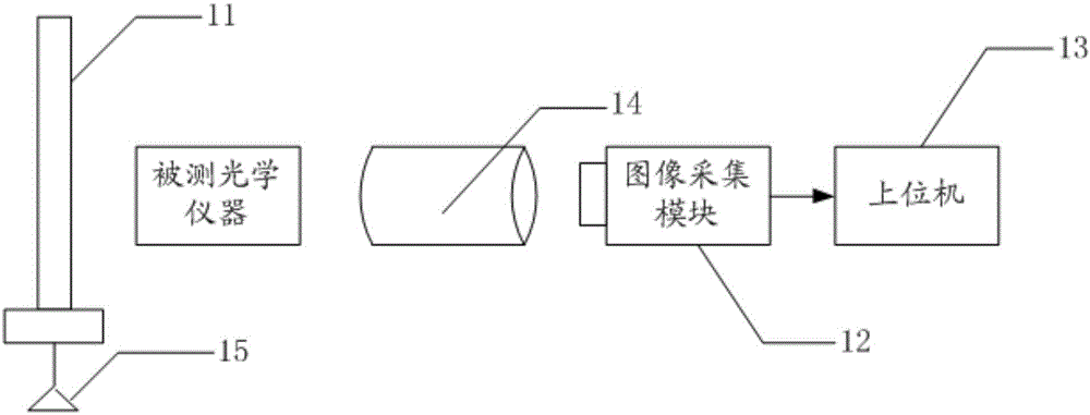
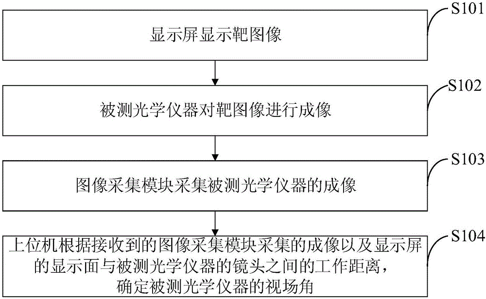
[0048] In view of the problems existing in the prior art, the embodiments of the present invention provide a detection device and detection method for the field angle of an optical instrument, so as to improve the detection accuracy and reduce the detection error.

[0049] In order to make the purpose, technical solutions and advantages of the present invention clearer, the present invention will be further described in detail below in conjunction with the accompanying drawings. Obviously, the described embodiments are only some of the embodiments of the present invention, rather than all of them. Based on the embodiments of the present invention, all other embodiments obtained by persons of ordinary skill in the art without making creative efforts belong to the protection scope of the present invention.

[0050] The detection device and detection method for the field angle of an optical instrument provided by specific embodiments of the present invention will be described in d...


PUM


Abstract

The invention discloses a detection device of a view field angle of an optical instrument and a detection method. The detection method comprises the following steps: displaying a target image on a display screen; imaging the target image through a detected optical instrument; acquiring an image of the detected optical instrument through an image acquisition module; determining the view field angle of the detected optical instrument by an upper computer according to the received image acquired by the image acquisition module and a working distance between a display surface of the display screen and a camera lens of the detected optical instrument. According to the detection device and the detection method, provided by the embodiment of the invention, the image of the target image of the detected optical instrument is acquired through the image acquisition module, and the view field angle of the detected optical instrument is determined according to the image by the upper computer, and observation and alignment do not need to be carried out by human eyes; a plurality of times of detection can be carried out and the repeatability is high; compared with a human eye detection method, the detection device and the detection method have relatively high precision and detection errors are reduced.

Description

technical field [0001] The invention relates to the technical field of image processing, in particular to a detection device and a detection method for the field angle of an optical instrument. Background technique [0002] In optical instruments, with the lens of the optical instrument as the apex, the angle formed by the two edges of the maximum range where the object image of the measured object can pass through the lens is called the Field of View (FOV for short). The field of view is one of the important optical parameters of an optical instrument, which can reflect the design ability and level of the optical instrument; by comparing the actual measured value with the theoretical design value, it can also indirectly reflect the processing and assembly level of the optical instrument. [0003] At present, the measurement of the field of view of optical instruments is mostly done by the human eye observing a specific target through an optical instrument, such as a ruler o...

Claims


Application Information

Patent Timeline
Patent Type & Authority Applications(China)
IPC IPC(8): G01C1/00G01M11/02
CPCG01C1/00G01M11/02
Inventor 王亚坤李牧冰林琳
Owner BOE TECH GRP CO LTD
Why Eureka
Try Eureka