A storage battery intelligent monitoring system

An intelligent monitoring and storage battery technology, applied in the direction of measuring electricity, measuring devices, measuring electrical variables, etc., can solve problems such as inaccurate acquisition of battery status, complex construction environment, hidden safety hazards, etc., to avoid time waiting and inconsistency, and achieve consistency Sexuality and real-time performance, the effect of preventing damage

Pending Publication Date: 2017-02-22
SHENZHEN POWER SUPPLY BUREAU
View PDF9 Cites 1 Cited by
  • Summary
  • Abstract
  • Description
  • Claims
  • Application Information

AI Technical Summary

Problems solved by technology

If these key data cannot be well grasped in real time, and abnormal batteries are not found and dealt with in time, there will be serious safety hazards, and even serious safety production accidents and property losses
[0003] At present, there are mainly two ways to test the state of the battery: 1) Use a portable battery testing instrument to manually test the battery (group). A lot of manpower and material resources, low efficiency, high cost, and poor data timeliness; 2) Use battery monitoring equipment to monitor the battery (group) online. Although the data can be processed and displayed on site, it can also be transmitted to a remote monitoring platform for monitoring processing and analysis, but due to the large number of test ports of battery monitoring equipment, a large number of lines (such as test lines, power lines and communication lines) need to be laid during installation, resulting in complex construction environment, heav

Method used


Image

  • A storage battery intelligent monitoring system
  • A storage battery intelligent monitoring system
  • A storage battery intelligent monitoring system

Examples


Example Embodiment

[0030] In order to make the objectives, technical solutions and advantages of the present invention clearer, the present invention will be further described in detail below with reference to the accompanying drawings.

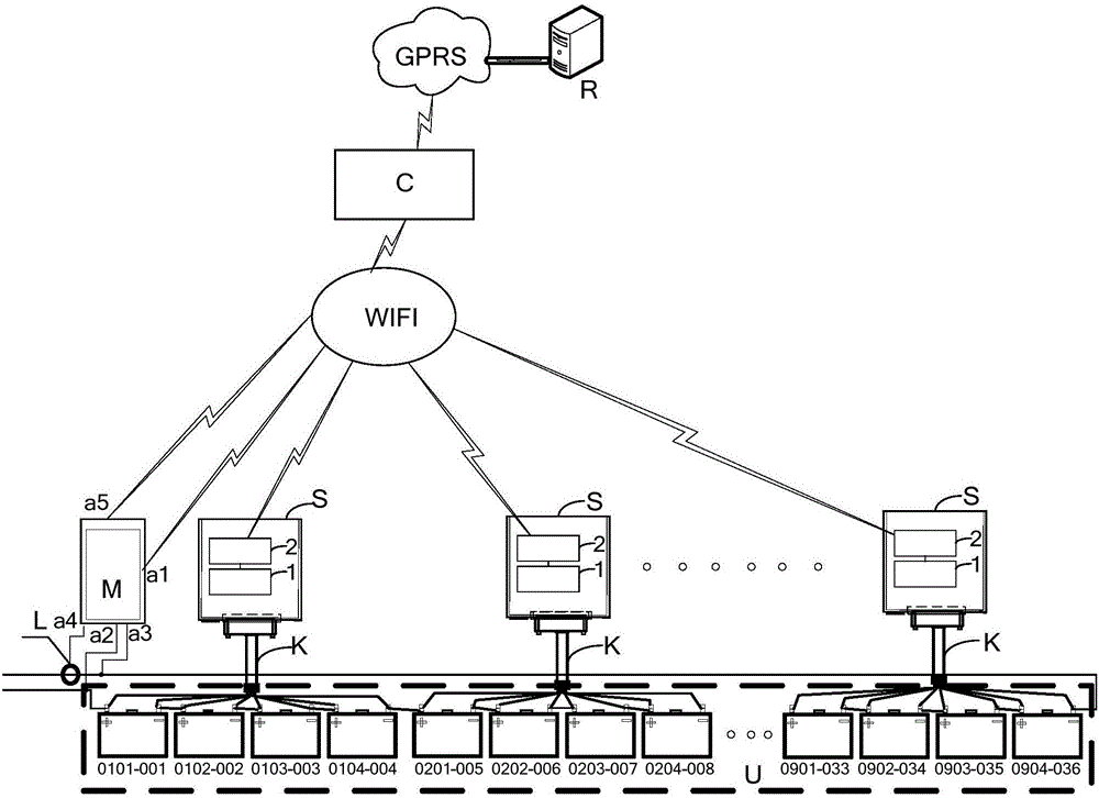
[0031] Such as figure 1 Shown is a battery intelligent monitoring system provided in an embodiment of the present invention. The battery intelligent monitoring system is matched with a plurality of battery packs each formed by a plurality of battery cells in series and / or in parallel, and has two phases. The adjacent battery packs are connected to each other to form a voltage source U to be tested; among them,

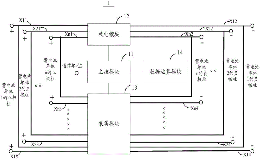
[0032] The battery intelligent monitoring system includes several battery monitoring devices S for real-time acquisition and calculation of the performance parameters of each battery cell in the corresponding battery pack, and one for real-time detection of the total voltage, total current and voltage ripple coefficient formed by the voltage source U to be te...


PUM


Abstract

The invention provides a storage battery intelligent monitoring system which cooperates with a plurality of storage battery packs. Each storage battery pack is composed of a plurality of storage battery cells which are in series and / or parallel connection, and each two adjacent battery packs are connected to each other to form a to-be-tested voltage source. The system comprises a plurality of storage battery monitoring devices, a controller and a centralized communication device. Each storage battery monitoring device includes a detection control unit and a communication unit arranged in series on a same circuit board. The detection control unit is also connected to each storage battery via a multi-core wire. The communication unit is also connected to the controller and the centralized communication device wirelessly; the controller is also connected with the to-be-tested voltage source and the centralized communication device; and the centralized communication device is also connected with a data receiving device. Through implementation of the invention, the inconvenience caused by manual detection and on-line monitoring of the storage batteries in the prior art can be solved to realize the consistency and real-time performance of properties and state parameter time of each battery in each storage battery pack and to obtain more accurate storage battery state parameters.

Description

Technical field [0001] The invention relates to the technical field of storage batteries, in particular to a storage battery intelligent monitoring system. Background technique [0002] With the development of technology, the acquisition of battery status information in the engineering application field is more and more refined and strict. Relying only on the battery voltage value, working current, and the remaining battery power estimated by the voltage cannot meet the existing needs, making the Accurate research and judgment of battery life cycle and fault status has become very important. The battery status is mostly expressed by parameters such as terminal voltage, internal resistance, remaining charge SOC (state of charge), SOH (state of health), and battery operating temperature. If these key data cannot be grasped well in real time, and abnormal batteries are not found and dealt with in time, there will be serious safety hazards, and even serious safety production acciden...

Claims


Application Information

Patent Timeline
IPC IPC(8): G01R31/36
CPCG01R31/3842
Inventor 杨忠亮王汝刚张胜宝李嫦艳周潮白海江
Owner SHENZHEN POWER SUPPLY BUREAU
Why Eureka
Try Eureka