Laser broadband fusion covering device

A wide-band, cladding technology, applied in the direction of laser welding equipment, optics, optical components, etc., can solve the problems of large overheating and undercooling of processed materials, cracking of molten layer, etc., and achieve the effect of reducing thermal stress

Active Publication Date: 2017-02-22
SUZHOU UNIV
View PDF10 Cites 15 Cited by
  • Summary
  • Abstract
  • Description
  • Claims
  • Application Information

AI Technical Summary

Problems solved by technology

[0009] However, the existing double-beam internal broadband powder feeding still has the following problems: due to the sudden cooling and sudden heating of laser cladding, the processing material will produce a large degree of overheating and undercoo

Method used


Image

  • Laser broadband fusion covering device
  • Laser broadband fusion covering device
  • Laser broadband fusion covering device

Examples


Embodiment Construction

[0028] The specific implementation manners of the present invention will be further described in detail below in conjunction with the accompanying drawings and embodiments. The following examples are used to illustrate the present invention, but are not intended to limit the scope of the present invention.

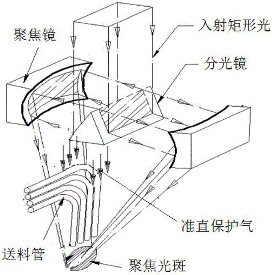
[0029]Please refer to Fig. 1, a laser broadband cladding device 10 shown in a preferred embodiment of the present invention converts the laser beam emitted by a laser (not shown) and projects it on the processing surface 20 for broadband laser cladding processing , the power used by the laser is 1000W-20000W, and the laser beam of the laser transmitter is transmitted by the optical fiber 50 . The laser broadband cladding device 10 is located above the processing surface 20 . The laser broadband cladding device 10 includes a collimating mirror 1 , a reflecting mirror 2 and a double-surface reflecting component 3 . The specification of the collimating mirror 1 is selected ...


PUM


Abstract

The invention relates to a laser broadband fusion covering device, and belongs to the field of 3D (three dimensional) formation. A laser beam sent by a laser can be converted and projected on a processing surface for broadband laser fusion covering processing by the laser broadband fusion covering device; the laser broadband fusion covering device comprises a reflecting mirror and a dual-molded- surface reflecting component; the laser beam is reflected to the dual-molded-surface reflecting component by the reflecting mirror; the dual-molded-surface reflecting component comprises an upper reflecting surface and a lower reflecting surface positioned under the upper reflecting surface; the upper reflecting surface is a parabolic focusing molded surface; the lower reflecting surface is a plane; after the upper reflecting surface receives the laser beam, the laser beam is reflected, so that a broadband focusing line spot is formed on the processing surface; after the lower reflecting surface receives the laser beam, the laser beam is reflected, so that a rectangular light spot is formed on the processing surface; the rectangular light spot is positioned at the outer side of the broadband focusing line spot. The laser broadband fusion covering device has the advantages that the technology heat treatment requirements of different materials and structures can be met; the defect probability of fusion layer residual thermal stress, cracks and the like is reduced.

Description

technical field [0001] The invention relates to a laser broadband cladding device, which belongs to the field of 3D forming. Background technique [0002] Laser direct 3D cladding deposition forming of metal and alloy parts, important functional surface cladding strengthening modification, repair and remanufacturing, etc. have great application value and The prospect is the key development direction of the developed countries at present. my country has also clearly listed the basic technology of metal additive manufacturing and the research and development of core basic components as key development areas. Among them, laser broadband cladding is an efficient laser cladding additive manufacturing technology. Laser broadband cladding has a large single-pass forming width, which can reach 10-40mm in one scan (narrow-band cladding is only φ1-5mm), so the cladding efficiency is high; large-area laser broadband cladding can also greatly reduce the number of laps and repeated hea...

Claims


Application Information

Patent Timeline
IPC IPC(8): G02B27/09G02B27/14C23C24/10
CPCG02B27/0911G02B27/0977G02B27/0983G02B27/14C23C24/10B22F12/44B22F12/55B22F12/70B22F2999/00B22F2007/042B22F10/25B23K26/0643B23K26/144B23K26/0608B23K26/067B23K26/34B22F7/04B33Y30/00Y02P10/25B23K26/60C23C24/08
Inventor 石拓石世宏史建军傅戈雁
Owner SUZHOU UNIV
Why Eureka
Try Eureka