Kinematics and dynamics solution method of underactuated mechanism with flexible kinematic pairs

A technique of dynamic equations and kinematics, applied in the field of numerical iteration

Inactive Publication Date: 2019-06-07
HEBEI UNIV OF TECH
View PDF5 Cites 0 Cited by
  • Summary
  • Abstract
  • Description
  • Claims
  • Application Information

AI Technical Summary

Problems solved by technology

[0006] Aiming at the deficiencies of the prior art, the technical problem to be solved by the present invention is to provide a method for solving the kinematics and dynamics of an underactuated mechanism with a flexible motion pair. Iterates and solves according to the same principle, that is, directly considers that the velocity and acceleration in different time intervals are step changes, and does not need to solve the velocity and acceleration through the integral method, which overcomes the inability to solve the problem due to the second-order non-holonomic constraints in the current underactuated mechanism. Drawbacks of doing integral iterations

Method used


Image

  • Kinematics and dynamics solution method of underactuated mechanism with flexible kinematic pairs
  • Kinematics and dynamics solution method of underactuated mechanism with flexible kinematic pairs
  • Kinematics and dynamics solution method of underactuated mechanism with flexible kinematic pairs

Examples


Embodiment 1

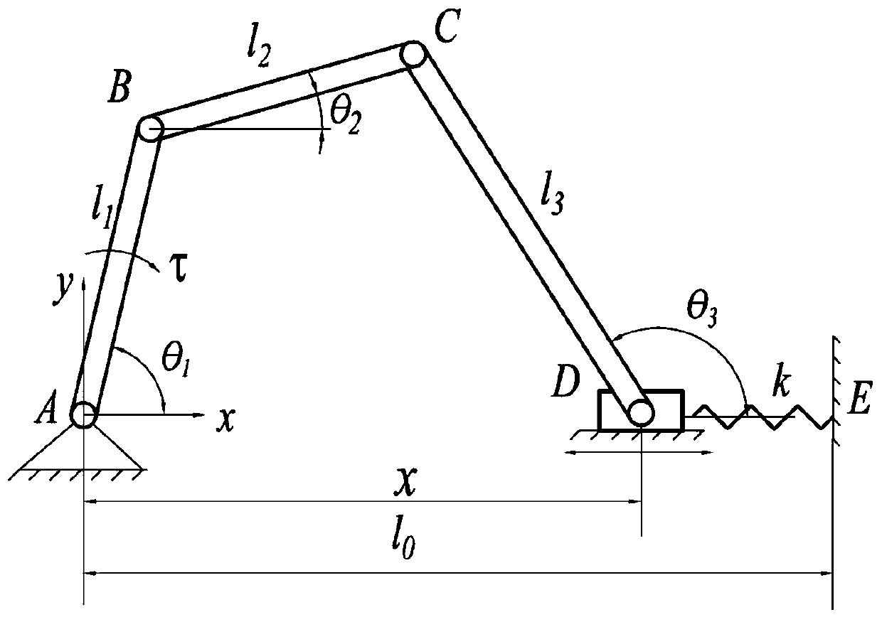
[0073] This embodiment takes the planar two-degree-of-freedom underactuated mechanism with flexible moving pairs as the research object, such as figure 1 As shown, establish the coordinate system of the mechanism, take point A as the coordinate origin, take the line AD as the x-axis, the direction pointing to D is the positive direction of the x-axis, and the vertical x-axis is the positive direction of the y-axis. The parameters of each component of the mechanism See Table 1.

[0074] Table 1 Component parameters of the underactuated mechanism with flexible kinematic pairs

[0075]

[0076] Define the mechanism parameters, establish the kinematics and dynamics models of the underactuated mechanism, select the iteration time step as 0.05s, and the number of iterations as 40 times. The specific modeling steps are as follows:

[0077] (2a) Use the closed vector method to establish the kinematic position equation of the mechanism:

[0078]

[0079](2b) Deriving the kinem...

Embodiment 2

[0106] This embodiment takes the underactuated mechanism with three degrees of freedom as the research object, such as Figure 6 As shown, establish the coordinate system of the mechanism, take point A as the coordinate origin, take the line AD as the x-axis, the direction pointing to D is the positive direction of the x-axis, the vertical x-axis is the positive direction of the y-axis, and the AB rod and BC rods are all moving parts. The solution process is the same as in Example 1.

[0107] What is not mentioned in the present invention is applicable to the prior art.


PUM


Abstract

The invention relates to a kinematics and dynamics solving iterative algorithm of an underactuated mechanism with a flexible kinematic pair. The algorithm includes the following steps: 1) establishing a coordinate system of the mechanism; 2) defining mechanism parameters, establishing a kinematic model and a dynamic model of the underactuated mechanism, and obtaining a kinematic position equation, a kinematic speed equation, a kinematic accelerated velocity equation and a dynamic equation of the mechanism; 3) giving initial condition of each component and a motion law of an original dynamic object, solving the kinematic equations and the dynamic equation of the mechanism at the time of t0, and obtaining the motion law of each component and the driving force of the original dynamic object at t0; 4) solving the kinematic equations and the dynamic equation of the mechanism at the time of tj, and obtaining the motion law of each component and the driving force of the original dynamic object at tj; 5) repeating the step 4 for n times so as to obtain the motion law of all components of the mechanism and the driving force of the original dynamic object in a whole motion cycle, drawing point by point by MATLAB, and obtaining motion raw curve of each component and a driving force change curve of the original dynamic object.

Description

technical field [0001] The invention relates to a numerical iteration method, in particular to a method for solving kinematics and dynamics equations of an underactuated mechanism with flexible motion pairs. Background technique [0002] The underactuated mechanism has the advantages of low energy consumption, light weight, and low cost due to the reduction of the driver, but its kinematics and dynamics constraints are incomplete, and the movement of the mechanism is uncertain. In the underactuated mechanism with flexible kinematic pairs , the elastic reaction force of the flexible kinematic pair can play the role of driving force, which can make up for the incompleteness of the dynamic constraints of the underactuated mechanism to a certain extent, but the addition of the flexible kinematic pair also makes the kinematics and dynamics of the mechanism more complicated. It is difficult to solve, but the solution of the kinematics and dynamic equations of the mechanism is the ...

Claims


Application Information

Patent Timeline
Patent Type & Authority Patents(China)
IPC IPC(8): G06F17/50
CPCG06F30/20
Inventor 张建军杜春翠杨高炜杨飞飞
Owner HEBEI UNIV OF TECH
Why Eureka
Try Eureka