
Label reception power prediction method of ultra high frequency (UHF) radio frequency identification (RFID) electronic toll collection (ETC) applications

A prediction method and received power technology, which is applied in special data processing applications, electromagnetic radiation induction, induction record carrier, etc., can solve the problems of time-consuming and laborious, difficult to accurately select statistical values, etc., and achieve high application value and high prediction accuracy Effect

Active Publication Date: 2017-02-22
HUNAN UNIV
View PDF7 Cites 9 Cited by
  • Summary
  • Abstract
  • Description
  • Claims
  • Application Information

AI Technical Summary

Problems solved by technology

[0005] The antenna radio frequency parameters and the scene reflection (scattering) geometric distribution of the typical application of UHF RFID technology have their own characteristics. There is a correlation between the field strength distribution in the identification range and the geometric characteristic parameters of the typical application scene, but it is hidden in the classic statistical channel. In the statistics of the model, it is difficult to accurately select the value of the statistics in practical applications
However, commercial simulation software based on Maxwell's equations can accurately predict the field strength distribution, but it is time-consuming and labor-intensive to first establish a 3D geometric and material model of the propagation scene.

Method used


Image

  • Label reception power prediction method of ultra high frequency (UHF) radio frequency identification (RFID) electronic toll collection (ETC) applications
  • Label reception power prediction method of ultra high frequency (UHF) radio frequency identification (RFID) electronic toll collection (ETC) applications
  • Label reception power prediction method of ultra high frequency (UHF) radio frequency identification (RFID) electronic toll collection (ETC) applications

Examples


Embodiment 1

[0088] step 1):

[0089] Refer to the national standard for short-range communication for electronic toll collection (GBT 20851.1-2007) and the ISO18000-6C standard to determine the geometric parameters and radio frequency parameters of the application scene, as shown in Table 1.

[0090] Table 1 Scenario test and simulation parameters

[0091]

[0092] Step 2):

[0093] Calculate the Cartesian coordinates of the hood reflection point;

[0094] Step 3):

[0095] Calculate the incident wave and reflected wave direction unit vector about the primary reflection on the ground and normal vector

[0096] Step 4):

[0097] If there is no primary reflection of the vehicle on the road, go to step 7, otherwise continue;

[0098] Step 5):

[0099] For the left and right vehicles, calculate the Cartesian coordinates P of the reflection point 2 and P 3 ;

[0100] Step 6):

[0101] Find the unit vector of the reflected wave and incident wave direction for the primary reflec...


PUM


Abstract

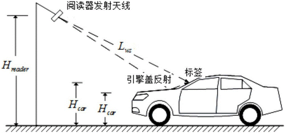
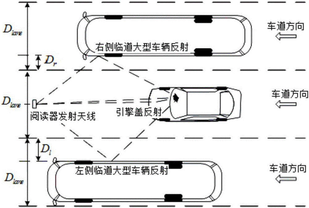
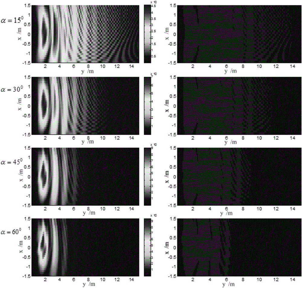
The present invention discloses a label reception power prediction method of UHF RFID ETC applications. The method comprises the steps of setting a reader antenna as a Cartesian coordinate origin, setting the Cartesian coordinate of a label as unknown, and solving a first-order reflection surface equation by the application scene geometrical parameters and the geometrical relationships, namely a plane equation of an automobile engine hood plane, a left temporary road vehicle right side surface and a right temporary road left side surface; by a free space radio wave propagation formula, calculating a visual range electric field intensity vector from the reader antenna to the label; separately calculating the coordinates of the reflection points on the above reflection surface; by a first-order reflection matrix equation of an electromagnetic wave, separately calculating the electric field intensity vectors of an incident wave and a reflection wave arriving at the label at the reflection surface; solving the label electric field vector sum, a label chip antenna port matching coefficient and a polarization matching coefficient, and finally obtaining a label reception power calculation result in the space. The label reception power prediction method of the present invention can obtain a higher prediction precision than the conventional lognormal model and Leslie Model, and obtain the prediction speed more convenient and faster than a commercial electromagnetic calculation software based on Maxwell's equations.

Description

technical field [0001] The invention relates to the field of electrotechnical technology, in particular to a tag receiving power prediction method for UHF RFID ETC application. Background technique [0002] The radio frequency identification (RFID) technology in the ultra-high frequency (UHF) frequency band has the characteristics of low tag cost, long recognition distance, and the ability to read multiple tags at a time. And the field of intelligent logistics has great application potential. In order to minimize the cost of the tag, the UHF RFID system uses wireless power transmission and backscatter modulation technology, and the tag needs to obtain energy from the electromagnetic wave radiated by the reader. The random multipath propagation of radio waves between the reader and the tag will lead to a certain proportion of blind spots in the identification area and reduce the identification reliability of the RFID system. This has been one of the main reasons restricting ...

Claims


Application Information

Patent Timeline
IPC IPC(8): G06K7/10G06F17/50
CPCG06F30/367G06K7/10217G06K7/10336G06K7/10415
Inventor 康志伟佘开骆坚
Owner HUNAN UNIV
Learn More