Energy center-based power-gas-heat system co-scheduling method and system

An energy center, collaborative dispatching technology, applied in the direction of resources, instruments, technology management, etc., can solve the problems of renewable energy generation restricting renewable energy application scenarios and utilization efficiency, wind farm curtailment and other issues

Inactive Publication Date: 2017-02-22
POWER GRID TECH RES CENT CHINA SOUTHERN POWER GRID +1
View PDF5 Cites 27 Cited by
  • Summary
  • Abstract
  • Description
  • Claims
  • Application Information

AI Technical Summary

Problems solved by technology

However, the fluctuation and intermittency of renewable energy power generation directly restrict the application scenarios and utilization efficiency of renewable energy, leading to the occurrence of wind farm curtailment and other phenomena.

Method used


Image

  • Energy center-based power-gas-heat system co-scheduling method and system
  • Energy center-based power-gas-heat system co-scheduling method and system
  • Energy center-based power-gas-heat system co-scheduling method and system

Examples


Embodiment 1

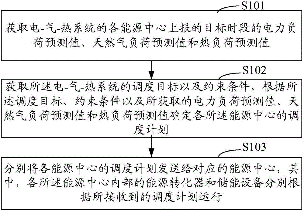
[0031] Embodiment 1 of the present invention provides an energy center-based electricity-gas-heat system coordinated scheduling method. The energy center-based electricity-gas-heat system coordinated scheduling method in this embodiment takes the processing process of the system scheduling mechanism as an example Be explained. figure 2 It is a schematic diagram of the implementation flow of the energy center-based electricity-gas-heat system collaborative scheduling method in Embodiment 1 of the present invention, as shown in figure 2 As shown, the energy center-based electric-gas-thermal system collaborative scheduling method in Embodiment 1 includes:

[0032] Step S101: Obtain the predicted power load value, natural gas load predicted value and thermal load predicted value reported by each energy center of the electric-gas-thermal system in the target period;

[0033] Here, the target time period can be selected according to actual needs, and it is generally better to cho...

Embodiment 2

[0106] Based on the first embodiment above, the second embodiment of the present invention provides an energy center-based electricity-gas-heat system coordinated scheduling system, see Figure 10 As shown, it is a schematic diagram of the composition and structure of the energy center-based electricity-gas-heat system coordinated dispatching system according to the second embodiment of the present invention Figure 1 ;Such as Figure 10 As shown, the energy center-based electric-gas-heat system collaborative scheduling system in this embodiment includes an acquisition unit 201, a processing unit 202, and a scheduling unit 203, wherein:

[0107] The obtaining unit 201 is used to obtain the predicted value of electric power load, predicted value of natural gas load and predicted value of thermal load reported by each energy center of the electric-gas-thermal system in the target period;

[0108] The processing unit 202 is configured to obtain the scheduling target and constrai...


PUM


Abstract

The invention relates to an energy center-based power-gas-heat system co-scheduling method and system. The method comprises the steps of obtaining a power load prediction value, a natural gas load prediction value and a heat load prediction value of a target time segment, reported by energy centers of power-gas-heat systems; obtaining scheduling goals and constraint conditions of the power-gas-heat systems, and determining scheduling plans of the energy centers according to the scheduling goals, the constraint conditions and the obtained power load prediction value, natural gas load prediction value and heat load prediction value; and sending the scheduling plans of the energy centers to the corresponding energy centers, wherein energy converters and energy storage devices in the energy centers run according to the received scheduling plans. By adopting the scheme, the co-scheduling of the power-gas-heat systems can be effectively realized.

Description

technical field [0001] The invention relates to the technical field of electric power system coordinated dispatch, in particular to an energy center-based electric-gas-thermal system coordinated dispatch method and system. Background technique [0002] With the increase in energy demand and environmental pressure, the third industrial revolution centered on the energy Internet is emerging. On the basis of research, scholars at home and abroad have proposed that the Energy Internet is a complex multi-network system formed by the power system as the core, renewable energy as the primary energy, and other systems such as natural gas networks and transportation networks. [0003] Under the framework of the Energy Internet, renewable energy will gradually replace traditional fossil fuels such as coal and become the main primary energy source. However, the fluctuation and intermittency of renewable energy power generation directly restrict the application scenarios and utilizatio...

Claims


Application Information

Patent Timeline
Patent Type & Authority Applications(China)
IPC IPC(8): G06Q10/06G06Q50/06
CPCY02P90/82G06Q10/06312G06Q50/06
Inventor 董朝阳郑宇赵俊华孟科张睿文福拴黄国日李杨
Owner POWER GRID TECH RES CENT CHINA SOUTHERN POWER GRID
Why Eureka
Try Eureka