Fire disaster smoke alarm with storage function

A technology for smoke alarms and storage functions, which is applied to electrical fire alarms, fire alarms, and fire alarms that rely on radiation to solve problems such as reduced alarm accuracy, analysis errors, and false alarms at the scene. , to achieve the effect of saving power consumption and improving accuracy

Active Publication Date: 2017-02-22
SHANGHAI TENSUN TRANSMART
View PDF10 Cites 20 Cited by
  • Summary
  • Abstract
  • Description
  • Claims
  • Application Information

AI Technical Summary

Problems solved by technology

At the same time, there will be a high-temperature combustion area at the fire scene, so different areas will have different temperature points on the scene, but for a relatively closed scene, the fire scene cannot be observed from the outside at the first time, and false alarms often occur As a result, due to false alarms, personnel retreated and firefighters ran in vain.
[0003] At present, photoelectric smoke and fire detectors are used in buildings. With the serious pollution of PM2.5, as well as dust, fog, moisture, and small oil droplets in the air, particles produced by aircraft transportation such as flower pollen particles, chicks, pigeons, etc. If the concentration of small fluff is too high, the particle concentration in the detection chamber of the photoelectric smoke detector will reach the threshold value, causing the current in the photoelectric tube to increase, thus reaching the fire alarm value prematurely and causing false alarms. Ensure that the alarm is triggered every time a fire occurs, but the accuracy of the alarm is reduced, resulting in huge losses due to false alarms
At the same time, the existing fire alarm will not have any reservations about the fire scene in the early stage of the fire after the alarm. Only experienced people can re-check the fire scene in the later stage to analyze the cause of the fire and the fire point.
The introduction of artificial experience value will bring analysis error

Method used


Image

  • Fire disaster smoke alarm with storage function
  • Fire disaster smoke alarm with storage function

Examples


Embodiment Construction

[0027] The content of the present invention will be described in further detail below in conjunction with the accompanying drawings and specific embodiments.

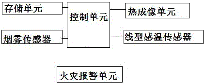
[0028] Such as figure 1 As shown, a fire smoke alarm with storage function, the alarm includes a control unit, a storage unit, a thermal infrared imaging unit, a plurality of smoke sensors, a plurality of linear temperature sensors, and a fire alarm unit;

[0029] The control unit is electrically connected to the storage unit, the infrared imaging unit, the smoke sensor, the infrared sensor and the ultraviolet sensor; the plurality of smoke sensors respectively measure the smoke concentration at their respective setting positions, and transmit the smoke data to the control unit ;

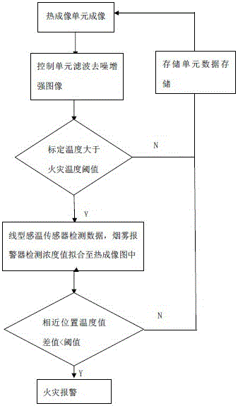
[0030] Such as figure 2 As shown, the infrared imaging unit shoots a thermal infrared image in the setting environment through an infrared camera, and stores the thermal infrared image data in the storage unit; after completing a complete ...


PUM


Abstract

The invention provides a fire disaster smoke alarm with a storage function. The alarm comprises a control unit, a storage unit, a thermal infrared imaging unit, a plurality of smoke sensors, a plurality of linear temperature induction sensors and a fire disaster alarming unit, wherein the control unit is used for acquiring an on-site thermal imaging image through the infrared imaging unit and analyzing a temprature point in a calibrated image; when a fire disaster point is judged, the control unit is used for starting the smoke sensors and the linear temperature induction sensors, fitting measured smoke data and temperature data to image data and analyzing and judging whether a difference value of temperature values in adjacent distances is smaller than a threshold value or not so as to judge whether a fire disaster occurs on site and preserve image data, temperature and smoke data of a fire disaster scene; and the accuracy of fire disaster alarming is improved, reasons of the fire disaster can be more directly judged and analyzed and data analysis of the fire disaster is carried out.

Description

technical field [0001] The fire smoke alarm of the present invention is suitable for the field of safety alarm, and in particular relates to the field of fire smoke alarm. Background technique [0002] When most fires occur, a large amount of smoke will be released. Smoke particles are one of the important early features of fires, so smoke detection can detect fires earlier. Smoke and fire alarms are now widely used in aircraft cabins, entertainment venues, server rooms, substations and other places. At the same time, there will be a high-temperature combustion area at the fire scene, so different areas will have different temperature points on the scene, but for a relatively closed scene, the fire scene cannot be observed from the outside at the first time, and false alarms often occur And cause the situation that personnel retreat and firefighters run in vain due to false alarm situation. [0003] At present, photoelectric smoke and fire detectors are used in buildings. ...

Claims


Application Information

Patent Timeline
Patent Type & Authority Applications(China)
IPC IPC(8): G08B17/06G08B17/10G08B17/12
CPCG08B17/06G08B17/10G08B17/125
Inventor 朱晶晶汪姗姗尹康
Owner SHANGHAI TENSUN TRANSMART
Why Eureka
Try Eureka