Display panel and device

A display panel and cover glass technology, which is applied in the direction of identification devices, optics, instruments, etc., can solve the problems of poor contrast of the display panel, and achieve the effect of improving contrast and reducing reflection

Inactive Publication Date: 2017-02-22
WUHAN CHINA STAR OPTOELECTRONICS TECH CO LTD
View PDF6 Cites 2 Cited by
  • Summary
  • Abstract
  • Description
  • Claims
  • Application Information

AI Technical Summary

Problems solved by technology

[0008] The purpose of the present invention is to provide a display panel and a device to solve the technical problem of poor contrast of existing display panels

Method used


Image

  • Display panel and device
  • Display panel and device
  • Display panel and device

Examples


Embodiment Construction

[0028] The following descriptions of the various embodiments refer to the accompanying drawings to illustrate specific embodiments in which the present invention can be practiced. The directional terms mentioned in the present invention, such as "up", "down", "front", "back", "left", "right", "inside", "outside", "side", etc., are for reference only The orientation of the attached schema. Therefore, the directional terms used are used to illustrate and understand the present invention, but not to limit the present invention. In the figures, structurally similar units are denoted by the same reference numerals.

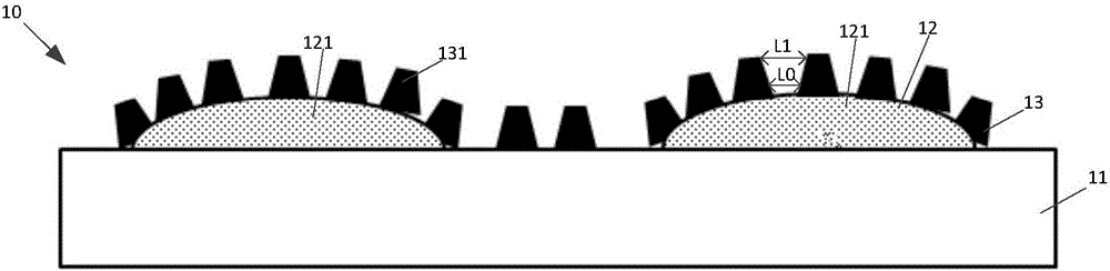
[0029] Please refer to figure 2 , figure 2 It is a cross-sectional view of a display panel according to an embodiment of the present invention.

[0030] Such as figure 2 As shown, the display panel 10 of the present invention includes a cover glass 11 , a first light adjustment layer 12 and a second light adjustment layer 13 . The first light adjustment layer ...


PUM


Abstract

The invention provides a display panel and device. The display panel comprises cover plate glass, a first light adjustment layer located on the cover plate glass, and a second light adjustment layer located on the first light adjustment layer, wherein the first light adjustment layer comprises at least two first microstructures; the first microstructures are used for improving the scattering rate of ambient light; the second light adjustment layer comprises at least two mutually spaced second microstructures; the second microstructures are used for increasing the transmittance of the ambient light. The display panel and device provided by the invention can reduce the reflection of the ambient light.

Description

[0001] 【Technical field】 [0002] The invention relates to the technical field of displays, in particular to a display panel and a device. [0003] 【Background technique】 [0004] Existing display panels emit light mainly through the principle of active light emission of the display device, but when sunlight is irradiated, the sunlight will be reflected on the surface of the panel, thereby affecting the contrast of the display screen. Especially for outdoor displays and display devices in indoor strong light source environments. [0005] The existing solution is to perform anti-reflection processing on the surface of the display device, such as figure 1 As shown, the existing display panel is provided with a multi-layer film 102 on the surface of the cover glass 101 . This method mainly uses the principle of light interference between film layers to reduce the reflection of ambient light. And the anti-reflection effect of this method depends on the optimal wavelength, and th...

Claims


Application Information

Patent Timeline
Patent Type & Authority Applications(China)
IPC IPC(8): G09F9/00G02B1/10
CPCG02B1/10G09F9/00
Inventor 崔宏青查国伟
Owner WUHAN CHINA STAR OPTOELECTRONICS TECH CO LTD
Why Eureka
Try Eureka