
Differential pair interface based on circulator

A differential pair and line interface technology, which is applied in the direction of waveguide devices, electrical components, circuits, etc., can solve the problems of unsuitable miniaturization and high integration, high production and development costs, and large circuit area, etc., to achieve compact structure, The form is simple, ensuring the effect of the overall structure

Active Publication Date: 2017-02-22
ANHUI SUN CREATE ELECTRONICS
View PDF7 Cites 2 Cited by
  • Summary
  • Abstract
  • Description
  • Claims
  • Application Information

AI Technical Summary

Problems solved by technology

The interconnection between the traditional 50Ω single-ended interface and the differential signal is realized by means of differential amplifier circuit or single-ended-differential converter. On the one hand, this kind of method has a large circuit area, which is obviously not suitable for the increasingly small In the design of highly integrated and highly integrated products; on the other hand, the structure is also relatively complex, which brings high production and development costs

Method used


Image

  • Differential pair interface based on circulator
  • Differential pair interface based on circulator
  • Differential pair interface based on circulator

Examples


Embodiment Construction

[0029] For ease of understanding, the specific implementation structure and workflow of the present invention are described below in conjunction with the accompanying drawings:

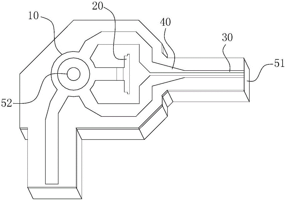
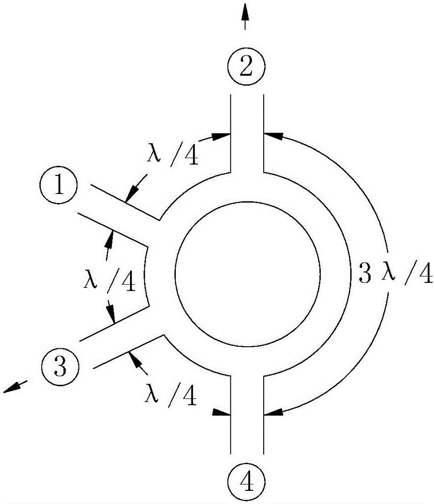
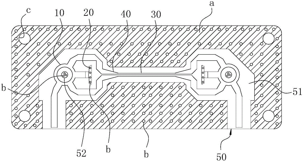
[0030] Concrete structure of the present invention, as Figure 1-2 As shown, it includes a dielectric plate 50 as a carrier. One side of the dielectric board 50 is covered with copper, while the other side is provided with a cavity structure; the cavity structure is covered with a structure such as figure 1 The planar microstrip plate a. The main structure of the planar microstrip board a includes a microstrip hybrid ring 10 , a 50Ω surface mount resistor 20 , a matching balun 40 and a differential pair 30 . Among them: refer to figure 2 As shown, the radio frequency signal is input by the microstrip hybrid ring 10, that is figure 2 The port ④ in the input is turned into an equal-amplitude anti-phase signal, and then the two output terminals are figure 2 The middle port ② and port ③ are finall...


PUM

PropertyMeasurementUnit
Heightaaaaaaaaaa
Thicknessaaaaaaaaaa

Abstract

The invention belongs to the field of PCB (printed circuit board) design, and particularly relates to a differential pair interface based on a circulator. The differential pair interface comprises a microstrip hybrid loop and a differential pair, an input end of the microstrip hybrid loop is connected with a 50-omega radio frequency port, an isolation end of the microstrip hybrid loop is connected with a 50-omega surface-mount resistor, an input port of each microstrip forming the differential pair is connected to the microstrip hybrid loop through a matching balun, the microstrip hybrid loop, the 50-omega surface-mount resistor, the matching balun and the differential pair are attached to one side face of a dielectric plate, another side face of the dielectric plate is coated with copper, and an air cavity is formed in the dielectric plate. The differential pair interface is compact in structure and high in working reliability, radio frequency signals can be directly transformed into differential signals on a PCB, and the differential signals are conveniently transmitted into a needed integrated chip. Besides, compactness and simplicity of a whole structure can be ensured, and products can be more miniaturized and integrated to meet application requirements.

Description

technical field [0001] The invention belongs to the field of PCB circuit design, in particular to a differential pair interface based on a circulator. Background technique [0002] In traditional wireless transceiver designs, 50Ω single-ended interfaces are widely used in RF and IF circuits, while in modern transceiver designs, differential interfaces are often used in high-frequency circuits for better performance. A single-ended signal is an unbalanced signal, measured by the difference between the signal and a fixed reference point; once a source of error is introduced into the signal path, problems can arise. Therefore, single-ended signals are susceptible to noise and electromagnetic coupling interference. Differential signals consist of pairs of balanced signals that are equal in magnitude and opposite in phase; the difference between the positive and negative balanced signals corresponds to the composite differential signal. If an error is introduced into a differen...

Claims


Application Information

Patent Timeline
IPC IPC(8): H01P1/38
CPCH01P1/38
Inventor 李霞孙浩胡卫东高静侯艳茹袁士涛吴莹莹
Owner ANHUI SUN CREATE ELECTRONICS
Learn More