Hook-shaped commutator

A commutator and hook type technology, applied in the field of commutators, can solve the problems of adhering bakelite powder, easy wear and tear of tools, affecting quality, etc., and achieves the effect of not easy to collapse, high bonding fastness, and ensuring mechanical strength.

Active Publication Date: 2017-02-22
ZHEJIANG SONGPU COMMUTATOR
View PDF1 Cites 6 Cited by
  • Summary
  • Abstract
  • Description
  • Claims
  • Application Information

AI Technical Summary

Problems solved by technology

However, if the width of the punching notch is small, although it is good for tracking and can better ensure the accuracy of the milling groove position, but the milling allowance is large and the tool is easy to wear; if the width of the punching notch is large, it cannot ensure the accuracy of the milling groove position. Accurate, and the bakelite powder is easy to collapse when milling grooves. After the material collapses, pits will be formed. The commutation copper sheet that should be hidden inside the bakelite powder matrix will be exposed, which not only affects the appearance and quality, but also seriously affects the commutation. The mechanical strength of the device; and due to the deviation of the position of the milling groove, the side of the punching gap is often not milled by the milling cutter, so it is easy to hang the material and stick to the bakelite powder, which seriously affects the appearance
In addition, when the elongated body in the background patent is arranged on the sheet-arranging plastic sleeve, because the last elongated body is likely to interfere with the top of the elongated body that has been inserted into the sheet-arranging plastic sleeve, it can only be arranged manually. Carrying out chip arrangement, the efficiency is low, and stable mass production cannot be achieved

Method used


Image

  • Hook-shaped commutator
  • Hook-shaped commutator
  • Hook-shaped commutator

Examples


Embodiment Construction

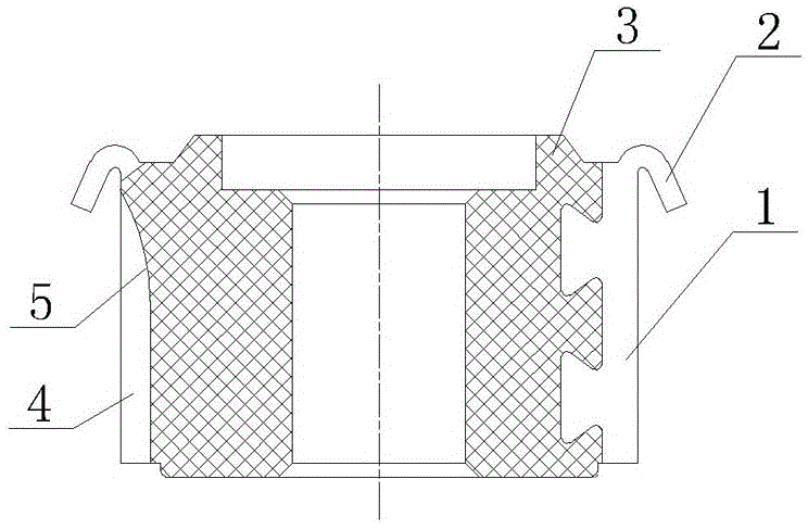
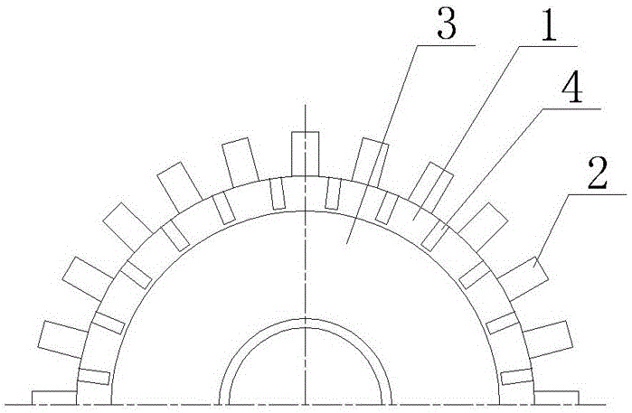
[0023] Such as figure 1 , 2 As shown, the hook-type commutator of the present invention is composed of a bakelite powder matrix 3 and twenty-four commutation copper sheets 1 arranged around the outer circle of the bakelite powder matrix 3, and the commutation copper sheets 1 There is a hook 2 on the top, the commutation copper sheet 1 and the bakelite powder matrix 3 are integrally injection molded, and the insulation groove 4 is milled out with a round milling cutter between adjacent commutation copper sheets 1 for inter-sheet insulation, and the insulation groove 4 The top of the arc transition 5 without being milled through.

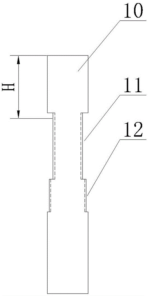
[0024] Such as Figure 3-9 As shown, the commutation copper sheet 1 is an elongated body 10 before the insulation groove 4 is milled and the hook 2 is formed. The inner surface of the elongated body 10 is provided with hook feet 13, and the outer surface of the elongated body 10 is a circular arc. Surface 14, the angle of circumference of arc surfa...


PUM


Abstract

The invention discloses a hook-shaped commutator composed of a bakelite powder base and commutating copper sheets. The hook-shaped commutator is characterized in that insulation between the commutating copper sheets is carried out by milling insulating grooves with a circular milling cutter between, the tops of the insulating grooves is subjected to arc transition so as to be prevented from being pierced; the commutating copper sheets are elongated bodies before the insulating grooves are milled and hooks are formed; the outer side of each elongated body is an arc surface, the height of the top, where a hook is to be formed, of the elongated body is H; the middle positions of the left and right sides of the elongated body are provided with connected upper and lower punching notches respectively, the distance between the top of the upper punching notch and the top of the elongated body is less than H; the width of the lower punching notch is narrow; the width of the upper punching notch is wide; the upper punching notch has a punching slope in the radial direction, the punching slopes of adjacent elongated bodies define a tapered mouth with an inward large end. The hook-shaped commutator prevents glue from entering the insulating grooves, enables high-quality production and high mechanical strength, and facilitates automatic insertion and mass production.

Description

technical field [0001] The invention relates to the technical field of commutators, in particular to a hook-type commutator. Background technique [0002] Hook-type commutator, including bakelite powder matrix and commutation copper sheets arranged in a circle on the outer circle of the bakelite powder matrix, the top of the commutation copper sheet is provided with a hook, One-piece injection molding. The hook type commutator has mica and no mica. The mica commutator is used to insulate the adjacent commutation copper sheets by setting mica sheets. The adjacent commutation copper sheets are insulated by milling out. slots for inter-chip insulation are mica-free commutators. The insulation slots of mica-free commutators are usually milled through up and down. In this way, after the commutator is assembled on the motor shaft, if the motor rotor coil requires glue treatment, Then the glue will enter the insulation groove along the motor shaft, which will adversely affect the...

Claims


Application Information

Patent Timeline
Patent Type & Authority Applications(China)
IPC IPC(8): H01R39/04
CPCH01R39/04H01R2201/10
Inventor 高志永潘光进曾汉佳潘光明肖友刚
Owner ZHEJIANG SONGPU COMMUTATOR
Why Eureka
Try Eureka