Three-phase dual-input inverter not having bridge arm shoot-through risk
A three-phase inverter, DC input voltage technology, applied in the direction of converting AC power input to DC power output, output power conversion device, electrical components, etc., can solve the problem of affecting the reliability of the inverter system, multi-level inverter Inverter circuit complexity, inverter output waveform quality deterioration, etc.
- Summary
- Abstract
- Description
- Claims
- Application Information
AI Technical Summary
Problems solved by technology
Method used
Image
Examples
Embodiment
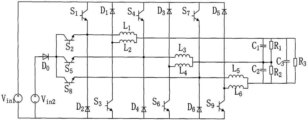
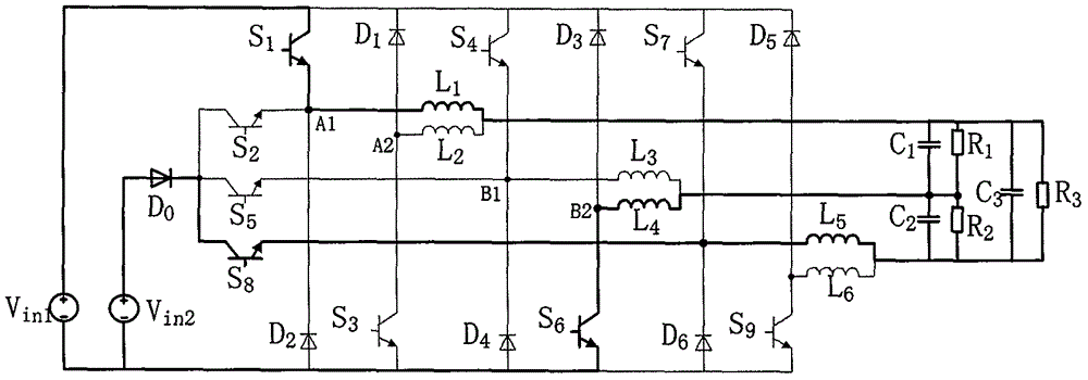
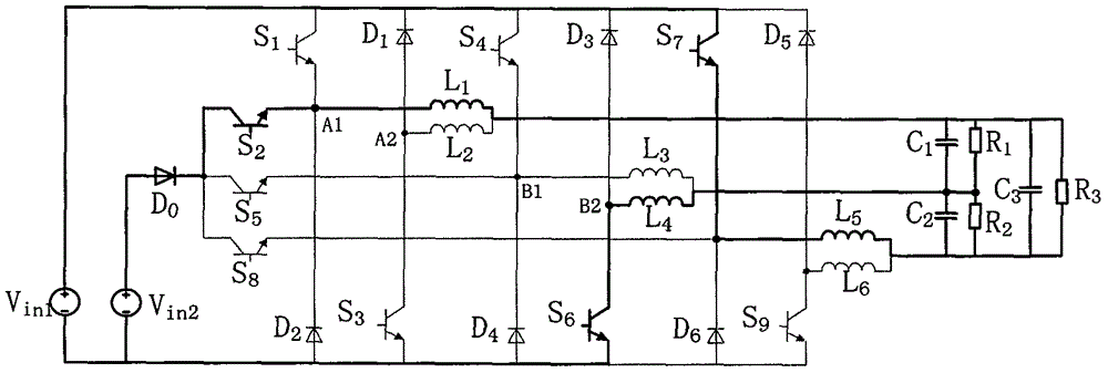
[0027] Example: such as figure 1 Shown is a three-phase dual-input inverter circuit structure without bridge arm shoot-through risk, including: two independent DC input voltage sources (V in1 ~V in2 ), nine switch tubes (S 1 ~S 9 ), seven diodes (D 0 ~D 6 ), six filter inductors (L 1 ~ L 6 ), three filter capacitors (C 1 ~C 3 ) and load (R 1 ~R 3 ).
[0028] The connection mode of the input power supply of the three-phase inverter is: V in1 The positive terminal of is connected to S 1 , S 4 , S 7 collector and D 1 、D 3 、D 5 negative pole; V in1 The negative terminal of the V in2 negative pole, D 2 positive electrode, S 3 emitter, D 4 positive electrode, S 6 emitter, D 6 positive electrode, S 9 the emitter. V in2 The anode of the diode (D 0 ), three switching tubes (S 2 , S 5 , S 8 ) into the circuit; D 0 The positive terminal is connected to V in2 the positive pole of the S 2 , S 5 , S 8 The collector is connected to D 0 negative pole; V i...
PUM
 Abstract
Description
Claims
Application Information
 - R&D
- Intellectual Property
- Life Sciences
- Materials
- Tech Scout
- Unparalleled Data Quality
- Higher Quality Content
- 60% Fewer Hallucinations
Browse by: Latest US Patents, China's latest patents, Technical Efficacy Thesaurus, Application Domain, Technology Topic, Popular Technical Reports.
© 2025 PatSnap. All rights reserved.Legal|Privacy policy|Modern Slavery Act Transparency Statement|Sitemap|About US| Contact US: help@patsnap.com


