Smart roaming tracking device and method employing bionic eagle eye

A tracking device, bionic eagle technology, applied in the field of bionic visual target recognition and tracking, can solve the problems of low resolution of large field of view images, short detection distance, etc., achieve high-resolution observation targets, overcome large distortion, and improve detection Effects of Efficiency and Accuracy

Active Publication Date: 2017-02-22
ARMY ENG UNIV OF PLA
View PDF5 Cites 7 Cited by
  • Summary
  • Abstract
  • Description
  • Claims
  • Application Information

AI Technical Summary

Problems solved by technology

[0004] The purpose of the present invention is to provide a bionic eagle eye intelligent roaming tracking device and tracking method to solve the problems of low resolution and short detection distance of traditional large field of

Method used


Image

  • Smart roaming tracking device and method employing bionic eagle eye

Examples


Embodiment 1

[0022] Embodiment 1: Bionic eagle eye intelligent roaming tracking device.

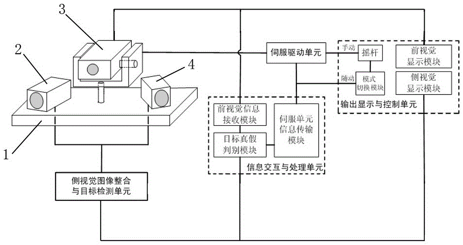
[0023] Such as figure 1 As shown, the bionic eagle eye intelligent roaming tracking device of the present invention includes a bionic eagle eye vision unit, a side vision image integration and target detection unit, an information interaction and processing unit, a servo drive unit, and an output display and control unit.

[0024] Wherein, the bionic eagle eye vision unit includes a left vision module 4, a right vision module 2 and a front vision module 3; The vision module 3 is arranged in the middle of the platform 1 . The left vision module 4 is integrated with the side vision image and connected to the target detection unit to form a left field of view; the right vision module 2 is integrated with the side vision image and connected to the target detection unit to form a right field of view. The left field of view and the right field of view form a large field of view with a partially overlappin...

Embodiment 2

[0032] Embodiment 2: Bionic eagle eye intelligent roaming tracking method.

[0033] see figure 1 , the bionic eagle eye intelligent roaming tracking method of the present invention comprises the following steps:

[0034] 1. Adjust the left vision module and right vision module so that there is an overlapping area of ​​8°~12° between the left field of view and the right field of view, and transmit the two signals to the side vision image integration and target detection unit for the left field of view Register and splicing with the images in the right field of view to synthesize a large airspace real-time surveillance scene; under this condition, the system real-time images the large field of view on the object side to monitor the large airspace information and extract interesting research targets from it or area.

[0035] 2. After the suspected target is found in the large airspace scene, the position information of the suspected target is obtained through image processing m...


PUM


Abstract

The invention relates to a smart roaming tracking device and method employing a bionic eagle eye. The roaming tracking device comprises a bionic eagle eye vision unit, a lateral vision image integration and object detection unit, an information interaction and processing unit, a servo drive unit and an output display and control unit. By adopting a binocular large-vision field image registration and splicing mode, a real-time surveillance airspace is expanded; the application ability of the smart roaming tracking device employing the bionic eagle eye in the field of bionic vision and object recognition is improved; the conditions of relatively large distortion caused by an over-large vision field angle of a traditional single lens and distortion of the spliced part caused by multiple small-vision field lenses are overcome; the requirements of large-airspace real-time surveillance of an object space scene are met; the target of high-resolution observation of an object is achieved; the object detection efficiency and accuracy are effectively improved; and meanwhile, the engineering application value is effectively improved through a human-computer integrated follow-up/manual tracking mode.

Description

technical field [0001] The invention relates to a bionic visual target recognition and tracking technology, in particular to a bionic eagle eye intelligent tracking device and a tracking method. Background technique [0002] Hawkeye is famous for its wide vision and sharp eyesight, which is inseparable from the physiological characteristics of eagle eyes. Unlike ordinary creatures, eagle eyes have two fovea on the retina - the central fovea and the lateral fovea. Based on the characteristics of the eagle eye, the bionic eagle eye vision technology has been maturely used in various ball games. At the same time, this technology can also be further applied to fields such as photoelectric detection, optical early warning, and situation monitoring. [0003] However, in the application of photoelectric detection, optical early warning, situation monitoring and other fields, there are problems of low resolution of large field of view images and short detection distance. Contents...

Claims


Application Information

Patent Timeline
IPC IPC(8): H04N7/18
CPCH04N7/181
Inventor 黄富瑜刘秉琦胡文刚武东生何永强张帅张雏徐春梅张鹏王元铂陈一超殷建玲
Owner ARMY ENG UNIV OF PLA
Why Eureka
Try Eureka