A closed liquid nitrogen self-circulation rapid cooling system

A rapid cooling and self-circulation technology, applied in induction heating, coil devices, etc., can solve the problems of shortening the service life of the electromagnetic wire, breaking the electromagnetic wire, and weakening the strength of the electromagnetic wire itself, so as to prevent the rupture, improve the use efficiency, and improve the The effect of using efficiency

Active Publication Date: 2019-04-19
GUANGDONG HI 1 NEW MATERIALS TECH RES INST CO LTD
View PDF4 Cites 0 Cited by
  • Summary
  • Abstract
  • Description
  • Claims
  • Application Information

AI Technical Summary

Problems solved by technology

However, since liquid nitrogen is easily vaporized under atmospheric pressure, when liquid nitrogen flows in from the inlet end of the central through hole of the electromagnetic wire and flows out from the outlet end of the central through hole of the electromagnetic wire, it is easy to produce a phase change, and the liquid nitrogen phase change process will cause The internal stress of the electromagnetic wire changes. With the extension of the working time of the electromagnetic wire, the strength of the electromagnetic wire itself will become weaker. In severe cases, the electromagnetic wire will be broken, thereby shortening the service life of the electromagnetic wire.

Method used


Image

  • A closed liquid nitrogen self-circulation rapid cooling system
  • A closed liquid nitrogen self-circulation rapid cooling system
  • A closed liquid nitrogen self-circulation rapid cooling system

Examples


Embodiment

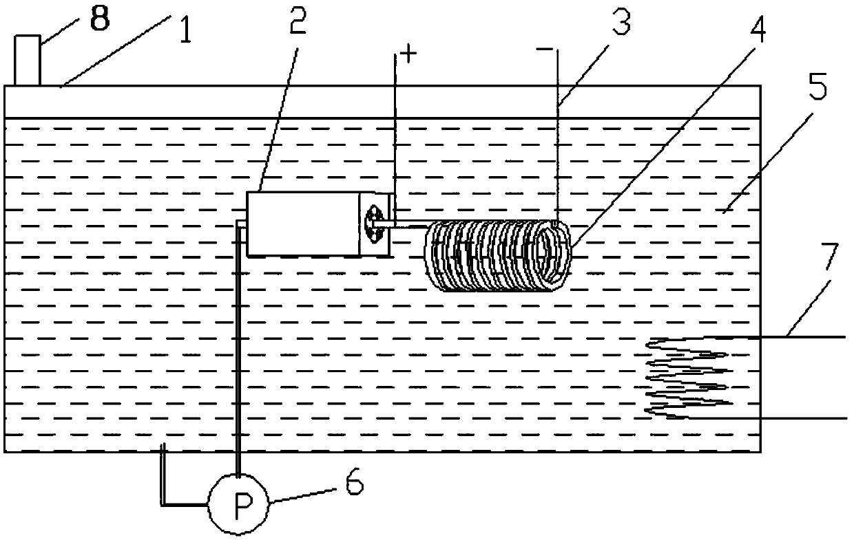
[0022] Embodiment: a closed liquid nitrogen self-circulation rapid cooling system.

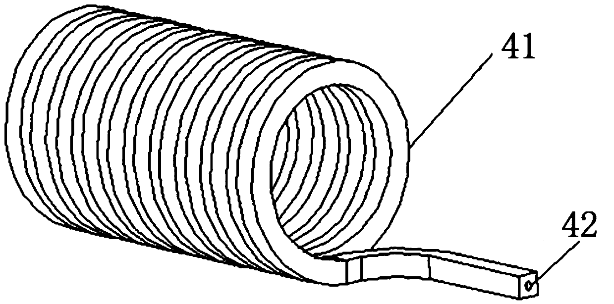
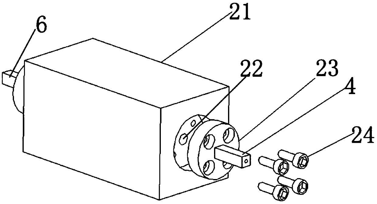
[0023] refer to figure 1 , figure 2 and image 3As shown, a closed liquid nitrogen self-circulation rapid cooling system includes: a liquid nitrogen tank 1, the liquid nitrogen tank 1 is a sealed liquid nitrogen tank, and the liquid nitrogen tank 1 is filled with liquid nitrogen 5; the lower liquid nitrogen tank 1 is installed The pressure relief valve 8 on the top, the pressure relief valve 8 is used to maintain the pressure in the liquid nitrogen tank 1 is always constant at an atmospheric pressure; the external cooling device 7 installed on the liquid nitrogen tank 1, the external cooling device 7 can be extremely fast freezing machine, the effect of the external cooling device 7 is to cool the liquid nitrogen 5 that has been increased in temperature after heat exchange to 65K; the liquid nitrogen pump 6 installed in the liquid nitrogen tank 1 or outside the liquid nitrogen tank 1; insta...


PUM


Abstract

The invention provides a closed liquid nitrogen self-circulation rapid cooling system. The closed liquid nitrogen self-circulation rapid cooling system comprises a liquid nitrogen tank, a pressure relief valve, an external cooling device, a liquid nitrogen pump, a low temperature insulating material connecting block, an electromagnetic coil and an energizing electrode, wherein the liquid nitrogen tank is closed and is filled with liquid nitrogen; the pressure relief valve and the external cooling device are arranged on the liquid nitrogen tank; the liquid nitrogen pump and the low temperature insulating material connecting block are arranged in the liquid nitrogen tank; the electromagnetic coil is arranged at one end of the low temperature insulating material connecting block; a central through hole is formed in the center of an electromagnetic lead in the electromagnetic coil; the central through hole of the electromagnetic lead is correspondingly connected with a central through hole of the low temperature insulating material connecting block; the energizing electrode is arranged on the electromagnetic coil. According to the closed liquid nitrogen self-circulation rapid cooling system provided by the invention, a mode of combining direct contact between liquid nitrogen and the electromagnetic lead for heat exchange with forced-convection heat transfer is adopted, and external heat dissipation and internal heat dissipation of the electromagnetic coil are simultaneously performed, so that the heat dissipating effect of the electromagnetic lead is greatly improved; meanwhile, the phenomenon that internal stress of the electromagnetic lead is changed due to the fact that liquid nitrogen flows through the central through hole of the electromagnetic lead can be prevented, and the service life of the electromagnetic lead is guaranteed.

Description

technical field [0001] The invention belongs to the technical field of rapid cooling, and in particular relates to a closed liquid nitrogen self-circulation rapid cooling system. Background technique [0002] At present, the electromagnetic coil usually adopts the cooling method of static oil cooling, that is, the coil sleeve is filled with fireproof oil, and the heat generated when the coil is energized is transmitted by the fireproof oil. The fireproof oil is in a static state in the coil sleeve, and the heat It completely relies on natural conduction, and reaches an equilibrium temperature of about 100°C after stable operation. Long-term operation at this temperature will shorten the life of the coil. [0003] In the field of scientific research and military applications, based on the need to generate a strong magnetic field, a pulsed high-power electromagnetic coil is often used. The power of each pulse is as high as several megawatts or even tens of megawatts. Most of t...

Claims


Application Information

Patent Timeline
Patent Type & Authority Patents(China)
IPC IPC(8): H05B6/42
CPCH05B6/42
Inventor 王伟史忠山
Owner GUANGDONG HI 1 NEW MATERIALS TECH RES INST CO LTD
Why Eureka
Try Eureka