
Lashing bridges for cargo ships

A technology for lashing bridges and cargo ships, which is applied in the direction of preventing the multi-way movement of goods, springs/shock absorbers, shock absorbers, etc. Simple, effect of reducing vibration tendency

Active Publication Date: 2019-11-05
MACGREGOR FINLAND
View PDF8 Cites 0 Cited by
  • Summary
  • Abstract
  • Description
  • Claims
  • Application Information

AI Technical Summary

Problems solved by technology

Systems with separate actuators, such as with cylinders or motors, are complex, expensive and prone to failure in their own right

Method used


Image

  • Lashing bridges for cargo ships
  • Lashing bridges for cargo ships
  • Lashing bridges for cargo ships

Examples


Embodiment Construction

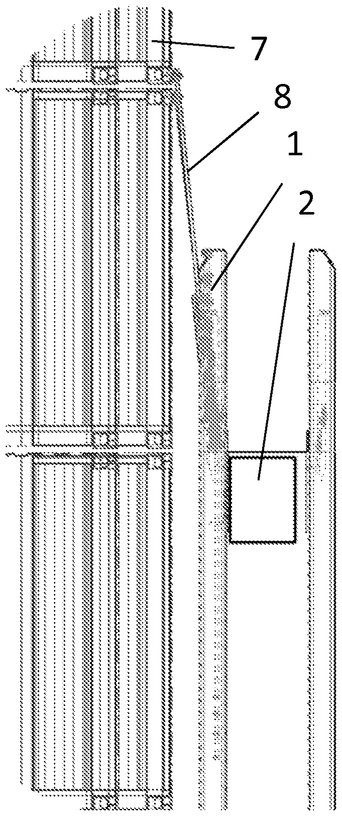
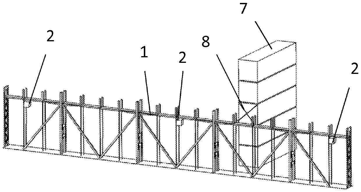
[0018] The lashing bridge 1 is usually arranged on the weather deck of the cargo ship in the transverse direction of the ship, and the containers / container stacks 7 are arranged between the lashing bridges in such a way that the lashing bars 8 of the containers can be fixed between the containers and the lashing bridge.

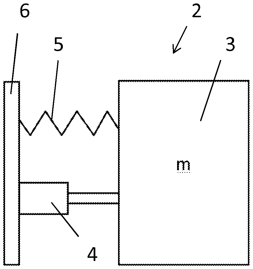
[0019] When a cargo ship travels at sea, the ship's engines and propellers generate vibrations in the ship's hull. This vibration acts as an excitation and generates vibrations in the lashing bridge 1 . figure 2 and 3 Indicates the vibration damper 2 fastened to the lashing bridge. The vibration damper 2 is usually fastened to the top part of the lashing bridge, but other locations are possible. When the lashing bridge 1 vibrates at its natural frequency as a result of the excited vibrations from the ship structure, the mass of the vibration damper 2 starts vibrating in a different phase, in which case the vibration of the lashing bridge 1 cannot move at i...


PUM


Abstract

Lashing bridge for a cargo ship, which lashing bridge is fixed directly or indirectly to hull structures of the cargo ship. The invention is implemented in such a way that at least one vibration damper is fastened in a fixed or detachable manner to the lashing bridge, which vibration damper comprises a mass element (3), which is connected to the lashing bridge via a flexible element (5) and / or via a damping element (4).

Description

technical field [0001] The object of the invention is a lashing bridge for cargo ships, which is fixed directly or indirectly to the hull structure of the cargo ship. Background technique [0002] A lashing bridge is a support frame to be installed on the deck of a cargo ship for transporting containers, to which lashing bars for supporting the containers are fixed. [0003] On a cargo ship, containers are typically carried below deck and above deck in rows and rows and also in layers one on top of the other. A detachable hatch is on the deck of the cargo ship, by means of which the cargo hold below is closed. The container is transported on top of the hatch. The supporting structures on deck for the containers (so-called lashing bridges) are mounted at a distance from each other such that the hatch covers can be removed and lowered back by means of a crane in connection with unloading and loading of the ship's cargo. [0004] After the containers have been loaded on boar...

Claims


Application Information

Patent Timeline
Patent Type & Authority Patents(China)
IPC IPC(8): B63B25/24F16F7/104F16F7/112F16F15/02B63J99/00
CPCB63B25/24B63J99/00F16F7/104F16F7/112F16F15/02
Inventor H.恩库里
Owner MACGREGOR FINLAND
Learn More