
a polarization rotator

A polarization rotator and waveguide technology, which is applied in the field of integrated optics, can solve problems such as unfavorable processing design and complex process, and achieve the effects of easy processing, eliminating sharp corner structures and reducing process difficulty.

Active Publication Date: 2019-08-20
HUAWEI TECH CO LTD
View PDF6 Cites 0 Cited by
  • Summary
  • Abstract
  • Description
  • Claims
  • Application Information

AI Technical Summary

Problems solved by technology

However, the process of this structure is complicated, which is not conducive to the processing design

Method used


Image

  • a polarization rotator
  • a polarization rotator
  • a polarization rotator

Examples


Embodiment Construction

[0032] The following will clearly and completely describe the technical solutions in the embodiments of the present invention with reference to the accompanying drawings in the embodiments of the present invention. Obviously, the described embodiments are only some, not all, embodiments of the present invention. Based on the embodiments of the present invention, all other embodiments obtained by persons of ordinary skill in the art without making creative efforts belong to the protection scope of the present invention.

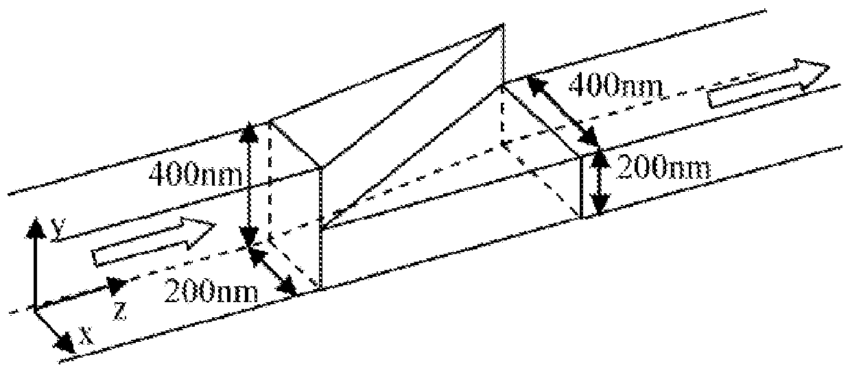
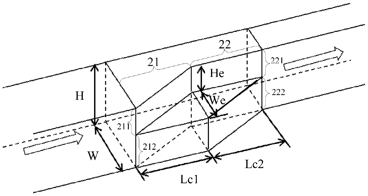
[0033] figure 2 It is a schematic diagram of the three-dimensional structure of Embodiment 1 of the polarization rotator of the present invention. An embodiment of the present invention provides a polarization rotator, which is used to realize the polarization rotation of light waves. For example, when a transverse electric wave (Transverse Electric Wave, TE for short) is input at the input end of the polarization rotator, the polarization rotation The outpu...


PUM


Abstract

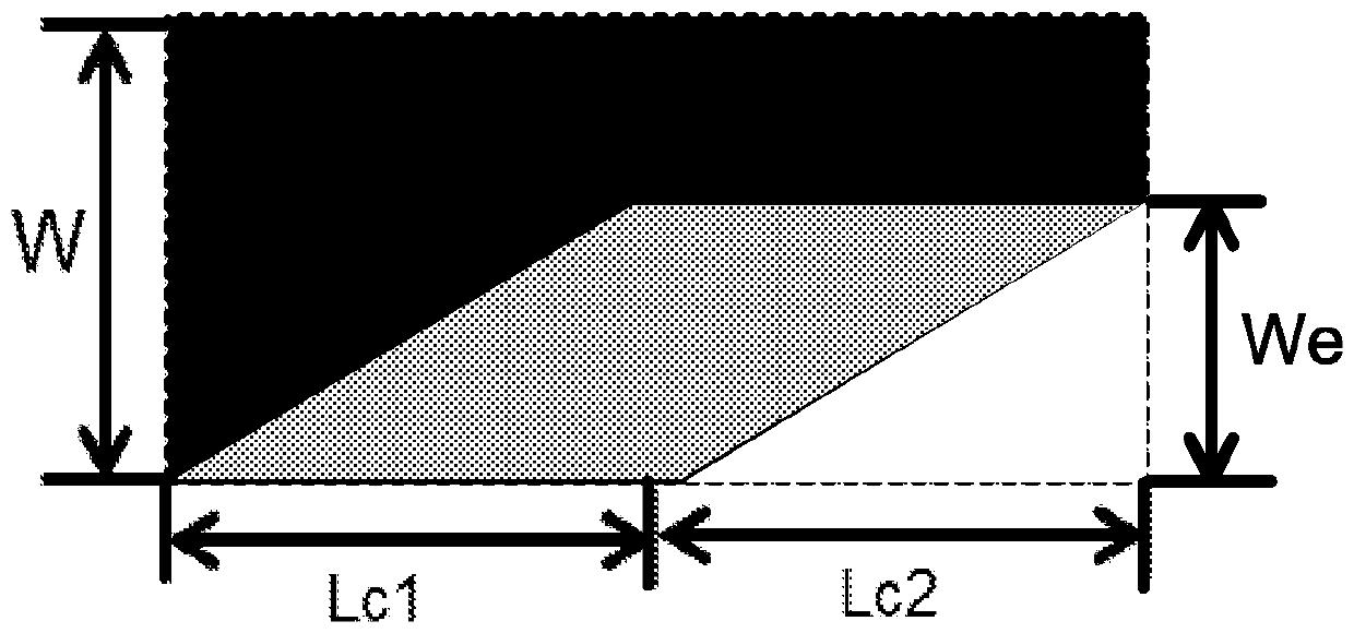
Disclosed is a polarization rotator (20), comprising a first stage waveguide (21) and a second stage waveguide (22). The second stage waveguide (22) and the first stage waveguide (21) are in cascade connection. The first stage waveguide (21) has the same thickness as the second stage waveguide (22). The first stage waveguide (21) comprises a first stage upper layer waveguide (211) and a first stage lower layer waveguide (212). In a direction from the first stage waveguide (21) to the second stage waveguide (22), the width of the first stage upper layer waveguide (211) gradually narrows from a first preset width (W) to a second preset width (W-We), while the first stage lower layer waveguide (212) keeps a consistent width. The second stage waveguide (22) comprises a second stage upper layer waveguide (221) and a second stage lower layer waveguide (222). The thickness of the second stage upper layer waveguide (221) is the same as that of the first stage upper layer waveguide (211), and in a direction from the first stage waveguide (21) to the second stage waveguide (22), the width of the second stage lower layer waveguide (221) gradually narrows from a first preset width (W) to a second preset width (W-We), while the second stage upper layer waveguide (221) keeps a consistent width. The structure of the polarization rotator (20) can be easily manufactured and implemented.

Description

technical field [0001] Embodiments of the present invention relate to integrated optical technology, and in particular to a polarization rotator. Background technique [0002] With the development of silicon-based photonics, optical devices based on silicon-on-insulator (Silicon on Insulator, SOI for short) have been extensively studied. However, due to the large structural birefringence of SOI, SOI-based optical devices have problems such as large polarization dependence, polarization mode dispersion, and polarization dependent loss. [0003] In order to avoid the above problems, a polarization diversity system is introduced to make SOI-based optical devices have better performance for various polarized lights by adjusting the polarization state of the light. Among them, the polarization rotator (Polarization Rotator, referred to as: PR), because of its simple structure and low cost, has become an important device in the polarization diversity system. [0004] In the prio...

Claims


Application Information

Patent Timeline
Patent Type & Authority Patents(China)
IPC IPC(8): G02B6/27G02B6/126
Inventor 周林杰谢安邦王涛
Owner HUAWEI TECH CO LTD
Learn More