
Method for operating a brushed commutator motor of an adjusting drive, and adjusting drive

A driving device and motor technology, applied in the direction of DC motor speed/torque control, motor control, power steering mechanism, etc., can solve the problems of adverse auditory impression load and load

Inactive Publication Date: 2017-02-22
BROSE FAHRZEUGTEILE GMBH & CO KG
View PDF6 Cites 0 Cited by
  • Summary
  • Abstract
  • Description
  • Claims
  • Application Information

AI Technical Summary

Problems solved by technology

This results in an unfavorable acoustic impression as well as a relatively high load and stress on the components of the control drive

Method used


Image

  • Method for operating a brushed commutator motor of an adjusting drive, and adjusting drive
  • Method for operating a brushed commutator motor of an adjusting drive, and adjusting drive
  • Method for operating a brushed commutator motor of an adjusting drive, and adjusting drive

Examples


Embodiment Construction

[0032] specific implementation plan

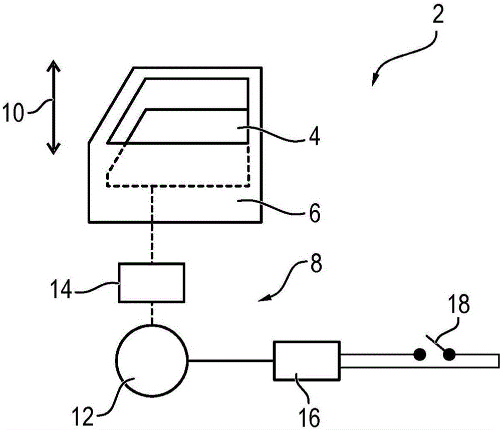
[0033] figure 1 An electric window regulator 2 is shown schematically with a window pane 4 , wherein the window regulator 2 is integrated in a door 6 of a motor vehicle. The window pane 4 is advanced along an adjustment path 10 by means of an adjustment drive 8 . The adjusting drive 8 includes an electric motor 12 , to which a worm gear 14 is assigned on the shaft side, by means of which the rotational movement of the electric motor 12 is converted into a translation of the window pane 4 . As soon as the motor vehicle occupant initiates the adjustment movement of the window pane 4 along the adjustment path 10 using the operating button 18 , the electric motor 12 is powered by the motor electronics 16 . Also integrated in the motor electronics 16 (also referred to as control electronics) is an anti-pinch protection which prevents the windshield 4 from pinching objects lying within the adjustment path 10 .

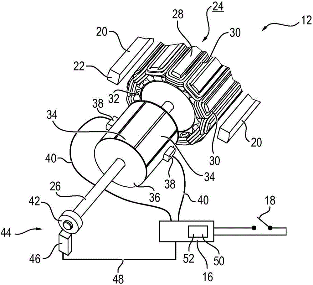
[0034] figure 2 An electric ...


PUM


Abstract

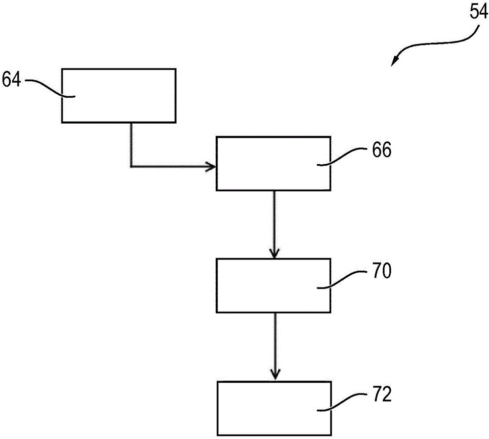
The invention relates to a method (54) for operating a brushed commutator motor (12) of an adjusting drive (8) in a motor vehicle, particularly a window lifter (2), having a rotor (24) and having a stator (22). An angular position (Alfa) of the rotor (24) with respect to the stator (22) is determined. The angular position (Alfa) is used to determine a ripple (60) within the torque (M), which ripple can be expected on the basis of the commutation. The motor current (I) is adapted such that the amplitude of the ripple (60) that can be expected remains below a determined limit value. The invention additionally relates to an adjusting drive (8) of a motor vehicle.

Description

technical field [0001] The invention relates to a method for operating a brushed commutator motor of an adjusting drive having such a commutator motor and to an adjusting drive of a motor vehicle. Part of the adjustment drive, especially the power window. Background technique [0002] Motor vehicles usually include adjustment elements, such as side windows and / or sliding sunroofs, which can be opened and closed using an electric adjustment drive. The seat, or at least parts of the seat, also have electric seat adjustment. The individual adjusting elements are moved by means of a transmission driven by an electric motor, in particular in the form of a worm gear with a worm (drive side) and a worm gear (output side) on the motor shaft. Conventionally, the transmission is arranged in a transmission housing, to which the electric motor is flanged via its motor housing (pole pot). The electric motor is usually fastened on its end side to the transmission housing, wherein the j...

Claims


Application Information

Patent Timeline
IPC IPC(8): H02P29/50H02P7/28H02P7/285E05F15/697
CPCH02P7/285E05F15/697E05Y2900/55H02P7/2805H02P29/50H02P2205/05
Inventor 马库斯·肖尔茨约尔格·于伯莱恩克里斯蒂安·托曼托马斯·魏因格特纳
Owner BROSE FAHRZEUGTEILE GMBH & CO KG
Learn More