Wind turbine blade with tripping device and method thereof

A technology of wind turbines and conversion devices, applied to wind engines that are consistent with the wind direction, configurations for installing/supporting wind engines, wind engines, etc., can solve problems affecting lift coefficients, etc.

Active Publication Date: 2017-03-01
YUANJIAN WIND POWER JIANGYINENVISION ENERGY CO LTD
View PDF8 Cites 7 Cited by
  • Summary
  • Abstract
  • Description
  • Claims
  • Application Information

AI Technical Summary

Problems solved by technology

The second deflector element is placed on the pressure side, which affects the minimum lift coefficient

Method used


Image

  • Wind turbine blade with tripping device and method thereof
  • Wind turbine blade with tripping device and method thereof
  • Wind turbine blade with tripping device and method thereof

Examples


Embodiment Construction

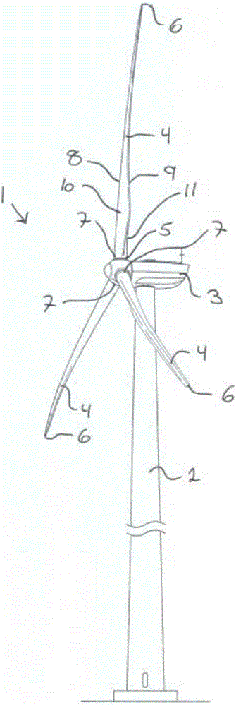
[0111] figure 1 An exemplary embodiment of a wind turbine 1 comprising a wind turbine tower 2 is shown. The nacelle 3 is arranged on top of the wind turbine tower 2 and is connected to the wind turbine tower 2 through a yaw mechanism (not shown). A rotor comprising at least two wind turbine blades 4 , here shown with three blades, is rotatably connected to a drive train arranged inside the nacelle 3 via a shaft. The wind turbine blades 4 are rotatably connected to the hub via a pitch mechanism 5 controlled by a pitch control system.

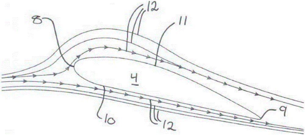
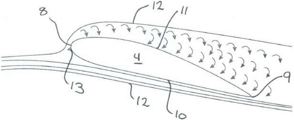
[0112] Each wind turbine blade 4 has a tip 6 , a root 7 and a body with an aerodynamic shape defining a leading edge 8 and a trailing edge 9 . The side surfaces of the aerodynamically shaped body define a pressure side 10 and a suction side 11 respectively.

[0113] FIG. 2 shows the air flow around a wind turbine blade 4 that is not equipped with a stall device on the pressure side 10 . The incoming wind strikes the wind turbine blade at an a...


PUM


Abstract

The present invention relates to a wind turbine and a method of reducing extreme loads and fatigue loads by using a passively activated tripping device arranged on the pressure side of the wind turbine blade. The tripping device is configured to interrupt the passing airflow, when activated, and transform the airflow into a turbulent airflow. The tripping device is positioned close to the leading edge, wherein its dimensions are optimised so that it reduces the maximum lift coefficient as well as increases the minimum lift coefficient which in turn reduces the range of the lift coefficient. The tripping device is activated at both negative and positive angle-of-attacks outside the normal operating range.

Description

technical field [0001] The present invention relates to a wind turbine with a wind turbine blade having one or more passively active air flow conversion devices arranged on a side surface near the leading edge of the wind turbine blade and a method therefor. The airflow diversion device is designed to interrupt laminar airflow chordwise over the wind turbine blade. The airflow diversion device is designed to reduce the extreme and fatigue loads experienced by wind turbines without compromising aerodynamic performance within the normal operating range. Background technique [0002] The main challenge when designing a wind turbine blade is to design a wind turbine blade that is structurally solid and has an aerodynamic profile that is stable both when the surface is clean and when it is rough, for example due to the accumulation of insects and dust. still able to run. One way of solving this problem is to provide a wind turbine blade with an aerodynamic shape that is insensi...

Claims


Application Information

Patent Timeline
Patent Type & Authority Applications(China)
IPC IPC(8): F03D1/06
CPCF03D1/0675F05B2270/331F03D13/10F05B2220/30F05B2240/221F05B2260/71Y02E10/728Y02E10/72F05B2240/3062F05B2240/122F03D13/20F03D1/0641
Inventor 孙毓平
Owner YUANJIAN WIND POWER JIANGYINENVISION ENERGY CO LTD
Why Eureka
Try Eureka