
Backlight module

A technology for a backlight module and a backplane, which is applied in the field of optical modules, can solve the problems of increasing the manufacturing cost and assembly process of the backlight module, and the bending deformation of the optical film, thereby achieving the effect of saving the manufacturing cost and the assembly process.

Active Publication Date: 2017-03-01
CORETRONIC OPTOTECHSUZHOU CO LTD
View PDF5 Cites 5 Cited by
  • Summary
  • Abstract
  • Description
  • Claims
  • Application Information

AI Technical Summary

Problems solved by technology

However, installing a diffuser plate will increase the manufacturing cost and assembly process of the backlight module, and omitting the diffuser plate will cause the optical film to bend and deform due to lack of supporting force

Method used


Image

  • Backlight module
  • Backlight module
  • Backlight module

Examples


Embodiment Construction

[0024] The aforementioned and other technical contents, features and effects of the present invention will be clearly presented in the following detailed description of a preferred embodiment with reference to the drawings. The directional terms mentioned in the following embodiments, such as: up, down, left, right, front or back, etc., are only referring to the directions of the drawings. Accordingly, the directional terms are used to illustrate and not to limit the invention.

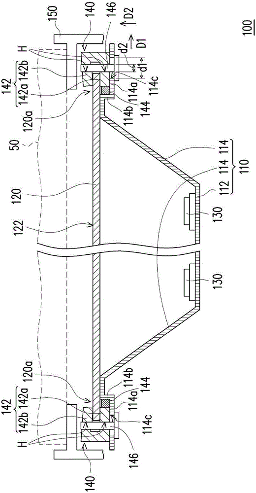
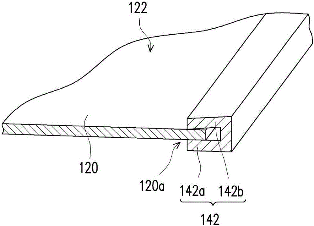
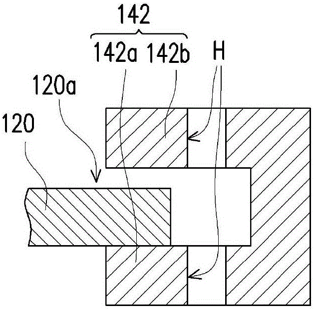
[0025] figure 1 is a schematic diagram of a backlight module according to an embodiment of the present invention. figure 2 yes figure 1 Partial perspective view of the clamping structure and the optical film. Please refer to figure 1 and figure 2 , the backlight module 100 of this embodiment includes a backplane 110 , an optical film 120 , a plurality of light sources 130 and two clamping components 140 . The backboard 110 includes a bottom board 112 and a plurality of side boards 114 connecte...


PUM


Abstract

The invention discloses a backlight module. The backlight module comprises a backboard, an optical diaphragm, at least one light source and at least one clamping assembly. The optical diaphragm is configured on the backboard. The light source is configured between the backboard and the optical diaphragm. The clamping assembly comprises a clamping structure and an elastic part. The clamping structure is configured on the backboard. One end part of the optical diaphragm is clamped in the clamping structure. The elastic part is configured between the clamping structure and the backboard. The clamping structure applies pulling force on the optical diaphragm through elastic force provided by the elastic part. The backlight module has following beneficial effects: without additional configuration of a dispersion board, the optical diaphragm is supported, thereby saving manufacture cost and assembly procedures of the backlight module.

Description

technical field [0001] The invention relates to an optical module, and in particular to a backlight module. Background technique [0002] With the increasing development of the semiconductor industry and related electronic industries, digital display devices such as smart phones (smart phones), notebook computers (notebooks), tablet PCs (tablet PCs), and flat-screen TVs are all developing in the direction of more convenience, multi-function and beauty. . When using these products, the display screen is an indispensable interface, and liquid crystal display devices (liquid crystal display, LCD) have become the mainstream of the display screen. [0003] Since the liquid crystal panel of the liquid crystal display device does not emit light, a backlight module (backlight module) must be provided under the liquid crystal panel to provide the required light for displaying images. For a direct type backlight module, generally, a diffuser plate and an optical film are arranged on...

Claims


Application Information

Patent Timeline
Patent Type & Authority Applications(China)
IPC IPC(8): F21S8/00F21V19/00F21Y115/10
CPCF21S8/00F21V19/001F21V19/0015F21V19/004
Inventor 徐麟颉
Owner CORETRONIC OPTOTECHSUZHOU CO LTD
Learn More