Solar heat pump huffing evaporator and water heater

A technology for solar heat pumps and evaporators, which is applied in the fields of inflation evaporators and solar heat pump water heaters, and can solve the problems of loud vibration and sound of refrigerant flowing in inflation evaporators, large plate area of ​​solar heat pump evaporators, and utilization rate of heat-absorbing areas. Low-level problems, to achieve the effect of suitable promotion and use, significant effect, and avoid turbulent flow of condensed water

Inactive Publication Date: 2017-03-01
QINGDAO ECONOMIC & TECHN DEV ZONE HAIER WATER HEATER
View PDF6 Cites 6 Cited by
  • Summary
  • Abstract
  • Description
  • Claims
  • Application Information

AI Technical Summary

Problems solved by technology

[0005] First: The refrigerant in the blowing evaporator flows and vibrates loudly in the blowing channel;
[0006] Second: The unreasonable flow channel scheme of the blown evaporator results in low utilization of the heat-absorbing area, and incomplete gasification of the refrigerant in the blown evaporator;
[0007] Third: After the

Method used


Image

  • Solar heat pump huffing evaporator and water heater
  • Solar heat pump huffing evaporator and water heater
  • Solar heat pump huffing evaporator and water heater

Examples


Embodiment 1

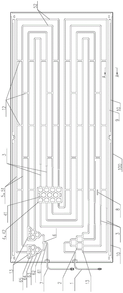
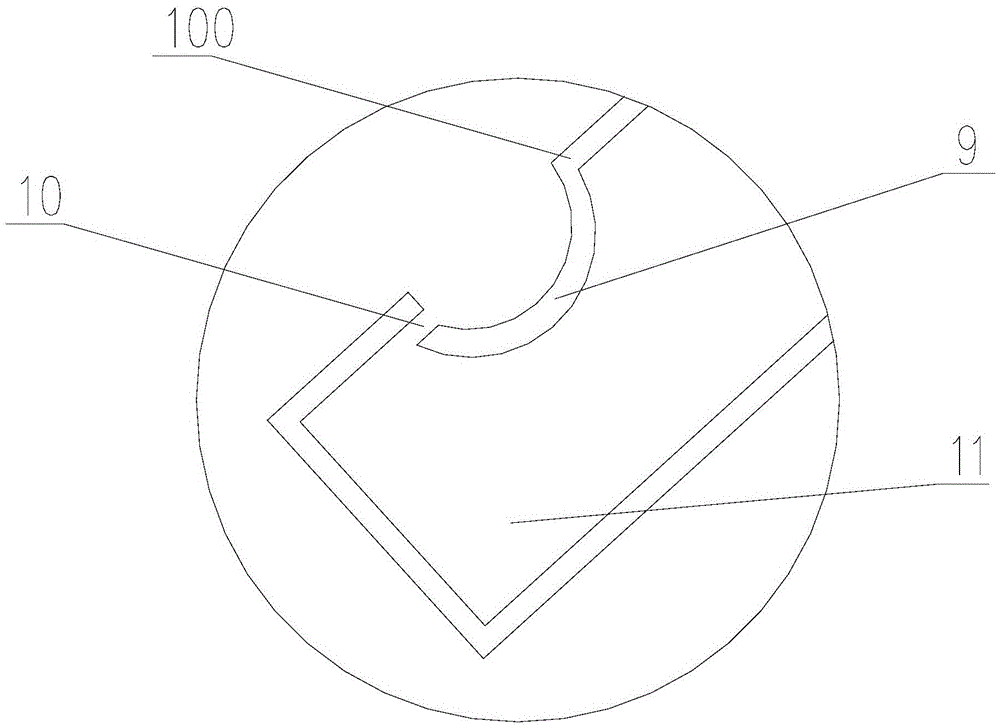
[0045] Such as figure 2 As shown, in this embodiment, the flow channels on the evaporator 100 include multiple heat exchange flow channels 5 arranged in parallel. The heat exchange channel 5 bends and extends in an "s" shape, coiling from the upper side to the lower side of the evaporator 100 . The heat exchange channel 5 includes a plurality of straight pipe sections 51 parallel to the axis of the evaporator 100, each straight pipe section 51 is arranged at intervals, and the ends of each straight pipe section 51 pass through a vertical pipe section 52 perpendicular to the axis of the evaporator 100 and Corresponding adjacent straight pipe sections 51 are connected, so that each straight pipe section 51 is connected in sequence to form an "s"-shaped flow channel. Therefore, the heat exchange channel 5 is curved and coiled on the entire plate surface of the evaporator 100 to increase the length of the heat exchange channel 5 as much as possible; The plate surface area is in...

Embodiment 2

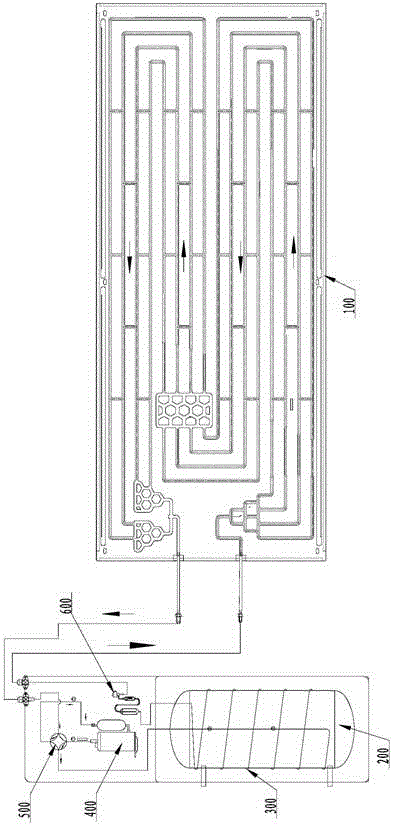
[0049] Such as figure 2 As shown, in this embodiment, the tree-like branch flow channel 2 includes a main pipe section 61 connected with the evaporator inlet 1, and the main pipe section 61 is respectively connected with two first-stage pipe sections 62 through a three-way joint, and the first-stage pipe section 62 are respectively connected to two second-stage pipe sections 63 through a three-way joint, and the second-stage pipe sections 63 are respectively connected to the inlet ends of the corresponding heat exchange channels 5 .

[0050] In this embodiment, the tree-like converging channel 6 includes a main pipe section 61 connected to the outlet 2 of the evaporator. The main pipe section 61 communicates with two first-stage pipe sections 62 through a three-way joint, and the first-stage pipe sections 62 respectively pass through The three-way joint communicates with two second-stage pipe sections 63 , and the second-stage pipe sections 63 communicate with the outlet ends...

Embodiment 3

[0056] Such as figure 2 As shown, in this embodiment, the honeycomb-shaped converging flow channel 4 includes a plurality of equilateral polygonal annular pipe sections 41; each annular pipe section 41 is arranged in multiple rows and columns, and adjacent sides of adjacent annular pipe sections 41 The sides share the same pipe so that the annular pipe sections 41 communicate with each other. Preferably, the annular pipe section 41 is in the shape of an equilateral hexagon, so as to increase the density of flow channels arranged on the evaporator plate per unit area as much as possible and increase the heat exchange efficiency of the evaporator.

[0057] In the present embodiment, the outer circumference of the converging flow passage 4 is provided with a square outer ring pipe section 42, and the ring pipe sections 41 near the outer side are respectively connected with the outer ring pipe section 42; One side goes into the connection and the opposite side goes out the conne...


PUM


Abstract

The invention relates to a solar heat pump huffing evaporator and a water heater. The evaporator is formed by pressing and huffing two plates; multiple heat exchange runners are arranged on the evaporator in parallel; an inlet of the evaporator is communicated with inlet ends of all the heat exchange runners by tree-shaped shunting runners; the middle parts of all the heat exchange runners are communicated with a honeycomb-shaped gathered shunting runner; and outlet ends of all the heat exchange runners are communicated with an outlet of the evaporator by a tree-shaped gathered runner. As the above runners are arranged on the evaporator, a refrigerant flowing through the puffing evaporator is totally vaporized, the panel utilization rate of the evaporator is prominently increased, and the heat sucking speed of the evaporator is accelerated; and meanwhile, the flowing speed of the refrigerant in the runners of the evaporator is controlled to be within a reasonable range, the problems of whole vibration and noise, caused by too fast flowing speed change of the refrigerant, of the evaporator are overcome. Meanwhile, the evaporator is simple in structure, prominent in effect and suitable for application and popularization.

Description

technical field [0001] The invention relates to a solar heat pump water heater in the field of water heaters, in particular to an inflation type evaporator of the solar heat pump water heater. Background technique [0002] At present, evaporators are mostly used in refrigerators, freezers, wine cabinets, air energy heat pumps and other products on the market. Solar heat pump evaporators appear in the market later, and the products are larger than refrigerators, freezers, wine cabinets, and air energy heat pump evaporators. Although it appeared late, solar heat pump water heaters have developed rapidly because of their advantages such as high heat conduction efficiency and fast heat exchange rate. [0003] As one of the main components in the heat pump system, the performance of the evaporator directly determines the heating performance and heat transfer coefficient of the solar heat pump system. At present, solar heat pump evaporators in the market mainly include finned eva...

Claims


Application Information

Patent Timeline
IPC IPC(8): F25B39/02F24J2/42F24H4/02F24S90/00
CPCY02E10/40F25B39/024F24H4/02F24S90/00F25B2339/022
Inventor 武光锋周志成李伟
Owner QINGDAO ECONOMIC & TECHN DEV ZONE HAIER WATER HEATER
Why Eureka
Try Eureka