Thermal barrier coating thermal-mechanical fatigue test device for gas environment

A thermal barrier coating, mechanical fatigue technology, applied in the field of aero-engine, can solve the problems of thermal barrier coating peeling off and other problems, and achieve the effect of easy operation

Active Publication Date: 2017-03-01
BEIHANG UNIV
View PDF6 Cites 17 Cited by
  • Summary
  • Abstract
  • Description
  • Claims
  • Application Information

AI Technical Summary

Problems solved by technology

These fatigue cracks grow and grow with the service time of the engine, and finally th

Method used


Image

  • Thermal barrier coating thermal-mechanical fatigue test device for gas environment
  • Thermal barrier coating thermal-mechanical fatigue test device for gas environment
  • Thermal barrier coating thermal-mechanical fatigue test device for gas environment

Examples


Embodiment Construction

[0034] The present invention will be described in further detail below in conjunction with the accompanying drawings.

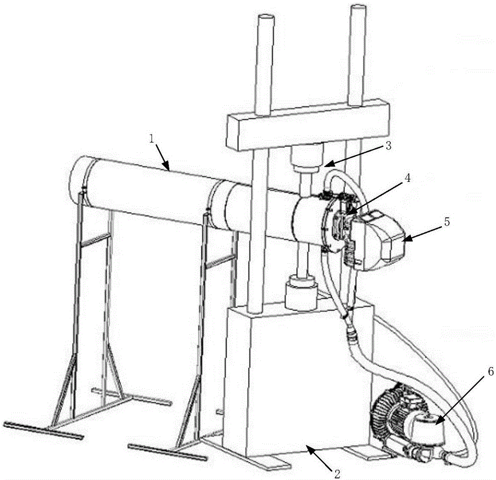
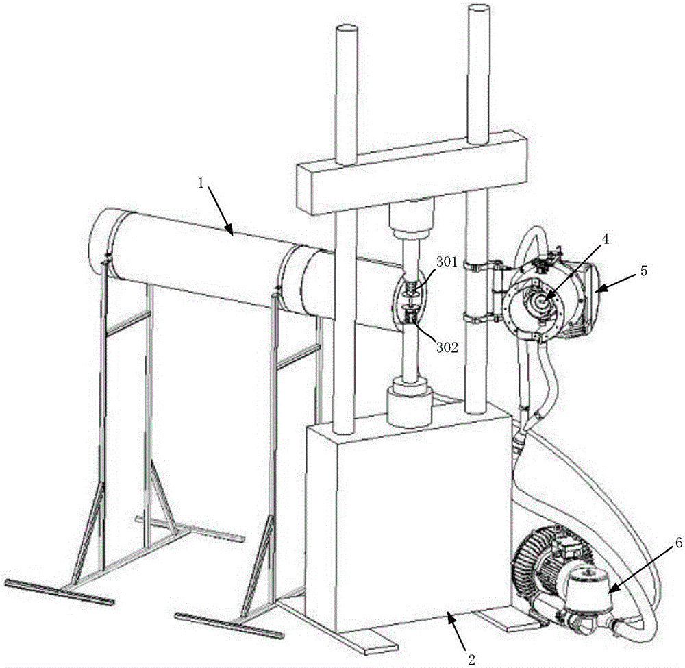
[0035] The thermal-mechanical fatigue test device of the thermal barrier coating under the gas environment of the present invention comprises a mounting sleeve 1, a universal testing machine 2, a sample attachment 3, a flame swinging part 4, a burner 5 and a high-pressure blower 6, such as figure 1 shown.

[0036] The installation sleeve 1 is supported by a bracket, and the axis is horizontally arranged between the upper clamp and the lower clamp of the universal testing machine 2 . The installation sleeve 1 is used for the installation of the flame swing part 4 and the burner 5 .

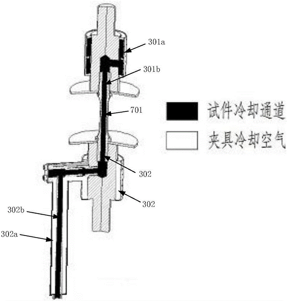
[0037] The sample attachment 3 is used to clamp and fix the sample 7; the sample attachment 3 and the sample 7 it holds are designed as an integrated structure, that is, each sample attachment 3 corresponds to a sample 7 . The sample attachment 3 comprises an upper connector 30...


PUM

PropertyMeasurementUnit
Lengthaaaaaaaaaa
Outer diameteraaaaaaaaaa
The inside diameter ofaaaaaaaaaa

Abstract

The invention discloses a thermal barrier coating thermal-mechanical fatigue test device for a gas environment. The device comprises a mounting sleeve, a universal testing machine, a sample loading member, a flame swinging part and a burner. The sample loading member is arranged in the mounting sleeve. The sample loading member is provided with upper and lower connectors. The upper and lower connectors are clamped by upper and lower clamps of the universal testing machine. A sample is fixed between the upper and lower connectors. The flame swinging part is a flame tube driven by a motor to swing and is installed on the end of the mounting sleeve, and the flame tube is located in the mounting sleeve. The burner produces high-temperature gas and sprays the high-temperature gas into the flame tube and the flame is sprayed to a sample through an outlet of the flame tube. By controlling flame tube swinging, a direction of high temperature gas is controlled so that the temperature of the sample produces high and low cyclic change. The test device realizes a fatigue life test on an aeroengine turbine blade thermal barrier coating under the mechanical cycle load and temperature cycle load and provides test data for aeronautical engine life estimation.

Description

technical field [0001] The invention relates to the field of aeroengines, and relates to a thermal-mechanical fatigue test device for a thermal barrier coating in a gas environment, in particular to a test device capable of simulating the thermal-mechanical fatigue working environment of a thermal insulation coating of a hot end part of an aeroengine. Background technique [0002] Aeroengine hot end components mainly refer to the combustion chamber and turbine components. Their working environment is very harsh. For example, the combustion chamber can produce gas with a temperature as high as 1700 ° C, and its own temperature is also close to the melting point of the material. Turbine blades are the power output components of aero-engines, which work in high-pressure, high-temperature and high-stress environments. The temperature of the gas around it has exceeded the melting point of the material used for the turbine blades. In order to reduce the working temperature of th...

Claims


Application Information

Patent Timeline
IPC IPC(8): G01N3/32
CPCG01N3/32G01N2203/0073G01N2203/0278
Inventor 齐红宇贾攀峰杨洪伟
Owner BEIHANG UNIV
Why Eureka
Try Eureka