
Horizontal decanter centrifuge

A decanter centrifuge and horizontal screw technology, applied in the field of centrifuges, can solve problems such as damage to sealing rings and bearings, damage to the inner wall of the drum, and reduction of solid particle cutting, so as to achieve smooth transmission, prolong service life, and reduce volume. Effect

Active Publication Date: 2017-03-08
SUZHOU RUIWEI CENTRIFUGAL SEPARATION TECH
View PDF9 Cites 5 Cited by
  • Summary
  • Abstract
  • Description
  • Claims
  • Application Information

AI Technical Summary

Problems solved by technology

The technical solution provided in this patent document is to consider the problem caused by the accumulation of solid phase particles, so the solution of setting a scraper at the end of the spiral small end cylinder is selected. However, due to the sharpness of the scraper, it is often easy to contact with the rotary The inner wall of the drum is cut, which causes damage to the inner wall of the drum. When a certain gap is formed between the scraper and the inner wall of the drum, even if the scraper can scrape off the accumulated particles, the particles will enter from the gap between the scraper and the drum. to the sealing ring and bearing, thus causing damage to the sealing ring and bearing
[0005] Secondly, it is often considered in the prior art that the solid particles in the liquid start to settle from the spiral wheel into the drum until the liquid phase is discharged from the large end of the drum. During this process, the solid particles gradually settle, and the coarse particles in them Settling faster, fine particles settling slower, some fine particles will not have time to settle and will be discharged out of the drum with the liquid
Based on the above considerations, the prior art would not think of cutting solid particles smaller
In reality, the volume of solid phase particles in many mixed liquids is relatively large, so they will collide with the drum and the screw in the drum, or even get stuck between the drum and the screw, which will cause the drum and the screw to collide with each other. It is easy to be damaged, which is why the service life of the existing horizontal screw discharge decanter centrifuge is often not high

Method used


Image

  • Horizontal decanter centrifuge
  • Horizontal decanter centrifuge
  • Horizontal decanter centrifuge

Examples


Embodiment

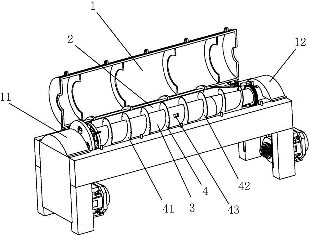
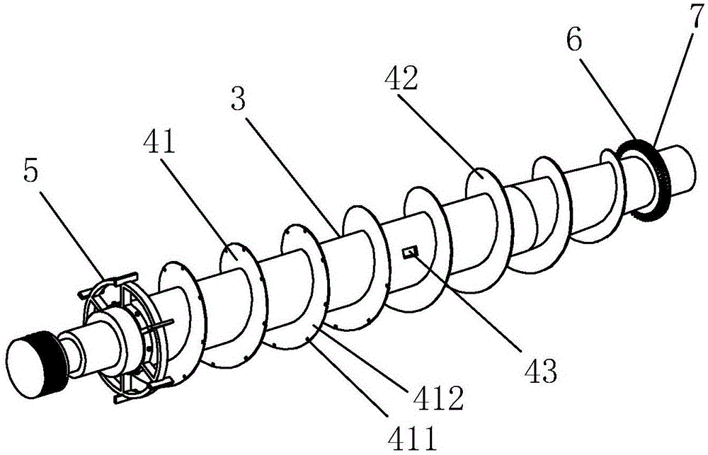
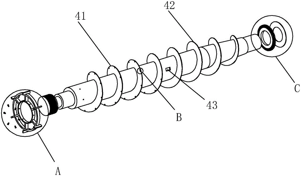
[0026] Embodiment: A horizontal screw discharge sedimentation centrifuge, including a shell 1, a screw pusher 3, a differential and a bearing seat, the screw pusher 3 includes a spiral blade 4, and the end of the screw pusher extends to the shell 1 outside and connected to the differential, a drum 2 is provided outside the screw propeller, a separation chamber is formed between the drum 2 and the inner wall of the shell 1, and an outer feed port and a solid phase are provided at the small diameter end 12 of the drum 2 The discharge port is provided with a liquid phase outlet at the large-diameter end 11 of the housing 1, the end of the helical blade 4 close to the small-diameter end 12 is the pushing end 42, and the end of the helical blade 4 close to the large-diameter end 11 is the cutting end 41, An inner outlet 43 is provided between the pushing end 42 and the cutting end 41, and the helical blade 4 is positioned at the cutting end 41 and is provided with several grooves 41...


PUM


Abstract

The invention discloses a horizontal decanter centrifuge. The key points of the technical scheme adopted by the invention are that the horizontal decanter centrifuge comprises a housing, a spiral pusher, a differential and a bearing pedestal. The spiral pusher comprises spiral blades. The tail end of the spiral pusher extends into the outer part of the housing and is connected with the differential. A revolving drum is arranged at the outer part of the spiral pusher. A separation chamber is formed between the revolving drum and the inner wall of the housing. An outer feed opening and a solid-phase discharge opening are formed in the minor diameter end of the revolving drum. A liquid-phase liquid outlet is formed in the major diameter end of the housing. One end, close to the minor diameter end, of each spiral blade is a pushing end. One end, close to the major diameter end, of each spiral blade is a cutting end. An inner discharge opening is formed between the pushing end and the cutting end. The spiral blades are located on the cutting ends. A plurality of grooves are formed in each spiral blade at intervals. Cutter bodies are formed between two adjacent grooves, and are arranged along the spiral lines of the spiral blades. According to the invention, the problem that a conventional horizontal decanter centrifuge is short in service life is solved.

Description

technical field [0001] The present invention relates to a centrifuge, more specifically, it relates to a horizontal screw discharge sedimentation centrifuge. Background technique [0002] The horizontal screw discharge sedimentation centrifuge utilizes the principle of obtaining different sedimentation velocities in the centrifugal force field by using the light, heavy liquid and solid phases with different densities and immiscibility in the mixed liquid to achieve separation and stratification or make the solid in the liquid The purpose of particle settling. It is widely used in chemical industry, light industry, food, mineral processing and other industrial sectors, and it is also an ideal equipment in environmental protection projects. [0003] The existing horizontal screw discharge decanter centrifuge is mainly composed of a high-speed rotating drum, a screw with the same steering direction as the rotating drum and a slightly higher or lower rotating speed than the rot...

Claims


Application Information

Patent Timeline
IPC IPC(8): B04B1/20B04B11/02B04B11/08
Inventor 王亚洲
Owner SUZHOU RUIWEI CENTRIFUGAL SEPARATION TECH
Learn More