Powder-bed additive manufacturing devices and methods

A powder bed and metal powder technology, applied in the field of powder bed additive manufacturing equipment, can solve the problem of not maintaining the thermal profile of the added layer

Active Publication Date: 2017-03-08
GENERAL ELECTRIC CO
View PDF8 Cites 9 Cited by
  • Summary
  • Abstract
  • Description
  • Claims
  • Application Information

AI Technical Summary

Problems solved by technology

For example, some powder bed fusion additive manufacturing techniques may not maintain an acceptable thermal profile in the added layer that forms the component during the build process, such as the cooling rate of the newly fused layer of metal alloy powder, or the cooling rate of the metal alloy powder. thermal gradient between the newly fused layer and the adjacent part of the component

Method used


Image

  • Powder-bed additive manufacturing devices and methods
  • Powder-bed additive manufacturing devices and methods
  • Powder-bed additive manufacturing devices and methods

Examples


Embodiment Construction

[0065] Reference will now be made in detail to exemplary embodiments of the present disclosure, examples of which are illustrated in the accompanying drawings. Wherever possible, the same reference numbers will be used throughout the drawings to refer to the same or like parts.

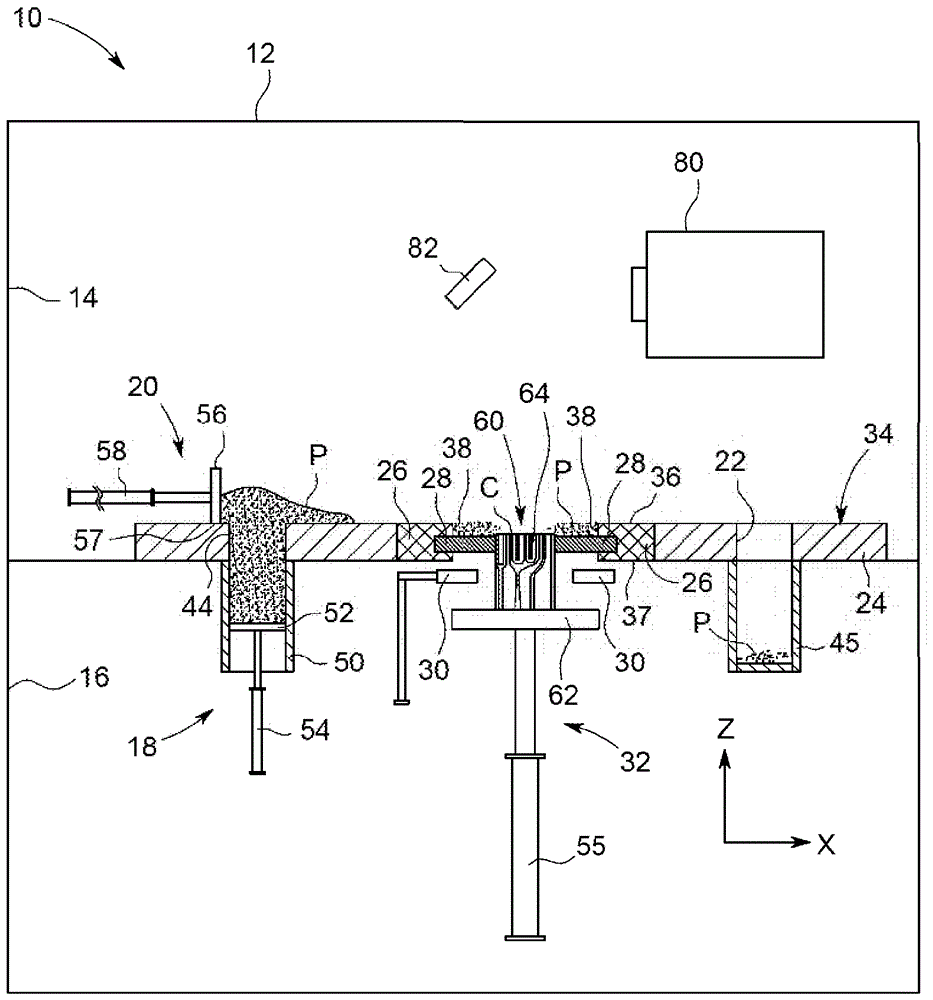
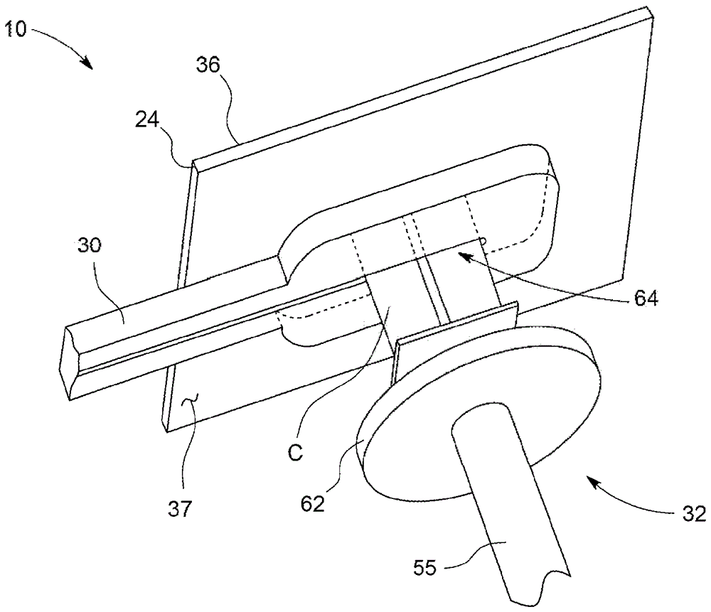
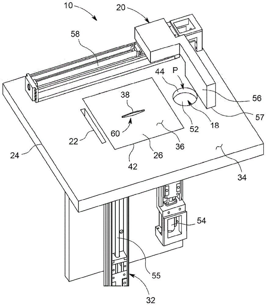
[0066] figure 1 An exemplary powder bed fusion additive manufacturing apparatus 10 for manufacturing or forming at least one metal alloy component free of cracks in accordance with the present disclosure is shown. In one example, the component is a crack-free high temperature superalloy component. The terms crack free and the like are used herein to mean that the layers of metal alloy components or component parts formed by the powder bed fusion apparatus 10 are free from thermally induced cracks in their microstructure after solidification. In one example, apparatus 10 is capable of forming metal alloy components (or portions thereof) via layers without thermally induced cracks approximately 100 mi...


PUM


Abstract

The disclosure relates to an apparatus (10) for manufacturing a metallic component (C), and corresponding methods. The apparatus (10) may include a build plate (26) with a build surface (36) and an aperture (38). The apparatus (10) may also include an actuator (55) operably to translate a metallic component (C) such that an end portion of the metallic component (C) is positioned within the aperture (38) of the build plate (26) and below the build surface (36). The apparatus (10) may further include a seal (28) coupled within the aperture (38) of the build plate (26) and configured to engage the end portion of the metallic component (C). The aperture (38) of the build plate (26), the seal (28), and the end portion of the metallic component (C) may cooperate to form a powder bed (60) to hold metallic powder (P) therein. The apparatus (10) may also include an external heat control mechanism (30) operable to form a predetermined temperature profile of the end portion of the component (C) to prevent cracking of the component (C).

Description

technical field [0001] The present disclosure generally relates to powder bed additive manufacturing apparatus and methods. More particularly, the present disclosure relates to powder bed additive manufacturing apparatus and methods for forming substantially crack-free components. Significant advances in high temperature materials have been achieved through formulations of Co-, Ni-, Ti- and Fe-based alloys conventionally referred to as "superalloys". These alloys are typically primarily designed to meet mechanical property requirements, such as creep resistance and fatigue strength. In this regard, modern metal alloys are widely used in high temperature applications, such as in gas turbine engines. Background technique [0002] Metal alloy components such as those of gas turbine engines are typically cast and / or machined. Typically, a one-shot core die (DCD) process is used to cast metal alloy components. The DCD casting method is often accompanied by the use of additive...

Claims


Application Information

Patent Timeline
Patent Type & Authority Applications(China)
IPC IPC(8): B22F3/105B22F5/04B33Y10/00B33Y30/00
CPCB22F3/003B22F12/17B22F10/28B22F10/30B22F12/90B22F12/30B22F2999/00B22F2203/03B22F2203/11B33Y10/00B33Y30/00B22F5/04B22F2003/1053B22F10/00B22F7/062C21D1/42B33Y50/02Y02P10/25B22F12/38B22F12/10B33Y80/00B22F10/10B22F12/00
Inventor W.T.卡特M.K.迈尔A.D.迪尔M.A.谢弗顿S.J.卡利塔M.F.X.吉利奥蒂
Owner GENERAL ELECTRIC CO
Why Eureka
Try Eureka