
Clamping rotating device

A rotating device and clamping technology, which is applied in the direction of expanding the mandrel, etc., can solve the problems of unrealized workpiece rotation, insufficient stability of the double clamp, insufficient clamping force, etc., to achieve convenient disassembly and maintenance, small space occupation, cost-saving effect

Active Publication Date: 2017-03-08
NANJING UNIV OF SCI & TECH
View PDF11 Cites 18 Cited by
  • Summary
  • Abstract
  • Description
  • Claims
  • Application Information

AI Technical Summary

Problems solved by technology

Chinese patent 201310405745.1 discloses a clamping device, which is a double clamping device, including a first clamping arm and a second clamping arm, the first clamping arm and the second clamping arm are hinged to each other, but For clamping rotary bodies, the double clamping grip is not stable enough, and the clamping is not strong enough
[0003] Chinese patent 201320076755.0 discloses a three-claw manipulator. The manipulator pushes the guide block to move along the tapered surface through the sliding of the telescopic rod to control the opening and closing of the claw fingers. It can grab the cylindrical workpiece, but the device does not realize the rotation of the workpiece. and not stable enough
However, the use of robot control greatly increases the cost

Method used


Image

  • Clamping rotating device
  • Clamping rotating device
  • Clamping rotating device

Examples


Embodiment Construction

[0018] The present invention will be described in further detail below in conjunction with the accompanying drawings.

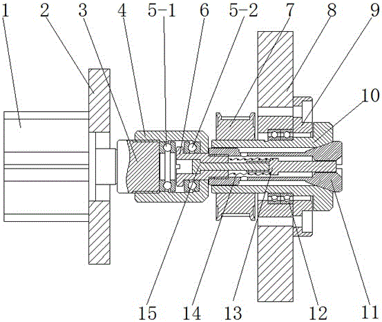
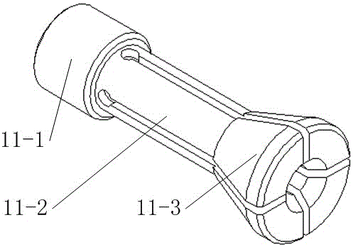
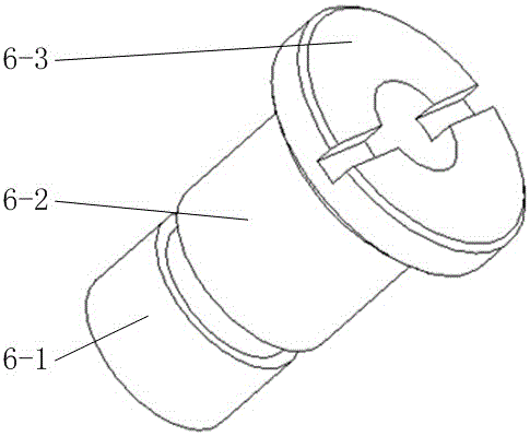
[0019] combine Figure 1-Figure 3 , A clamping and rotating device includes a stretching mechanism, a clamping and pressing mechanism and a turning mechanism. The clamping and pressing mechanism is arranged at the center of the slewing mechanism, and one end of the clamping and pressing mechanism is fixedly connected with the stretching mechanism.

[0020] The stretching mechanism includes cylinder 1 (commercially available, AirTAC SDA50x5-S), cylinder mounting plate 2, adapter stud 3, bearing mounting seat 4, first thrust ball bearing 5-1, second thrust ball bearing 5- 2 and the bearing connecting bolt 6. The center of the cylinder mounting plate 2 is provided with a circular hole, the piston rod of the cylinder 1 passes through the circular hole, the cylinder 1 is fixedly connected to the cylinder mounting plate 2 by bolts, and one end of the transfer stu...


PUM


Abstract

The invention discloses a clamping rotating device. The device comprises a stretching mechanism, a clamping compressing mechanism and a rotating mechanism; during work, a workpiece is ejected in from a center through hole of a round table of an elastic clamping sleeve, a spring is compressed, an air cylinder is ventilated, the elastic clamping sleeve is forced to move along a bearing sleeve in the direction where the air cylinder is located, radial shrinkage is carried out, and the aim of clamping an object is achieved; a synchronous belt wheel does the rotation motion, and the elastic clamping sleeve and the workpiece are driven to jointly do the rotation motion; if the air cylinder carries out exhaust unloads, the elastic clamping sleeve is reset, and the spring is automatically reset and meanwhile ejects out the workpiece. Stable clamping and rotating of the workpiece can be achieved, the problem that due to double clamping grasping, clamping stability is poor, and clamping force is not enough is solved, the control manner that the air cylinder is combined with a mechanical mechanism is adopted in the device, operation is convenient, and the cost is saved.

Description

technical field [0001] The invention belongs to the technical field of mechanical processing equipment, and in particular relates to a clamping and rotating device. Background technique [0002] At present, in the field of industrial automation, there are many clamping devices, such as double clamping, triple clamping, multi clamping and so on. Chinese patent 201310405745.1 discloses a clamping device, which is a double clamping device, including a first clamping arm and a second clamping arm, the first clamping arm and the second clamping arm are hinged to each other, but For the clamping rotary body, the double clamping is not stable enough, and the clamping is not strong enough. [0003] Chinese patent 201320076755.0 discloses a three-claw manipulator. The manipulator pushes the guide block to move along the tapered surface through the sliding of the telescopic rod to control the opening and closing of the claw fingers. It can grab the cylindrical workpiece, but the devi...

Claims


Application Information

Patent Timeline
IPC IPC(8): B23B31/40
CPCB23B31/4013B23B31/4026
Inventor 王波
Owner NANJING UNIV OF SCI & TECH
Learn More