Upper Shoulder Bowl Compression Molding Type Shoulder Injection Machine

A molding type, shoulder injection machine technology, applied in coating and other directions, can solve the problems of inconvenient mold replacement, low production efficiency, high cost of use, and achieve the effects of easy dust-free sterilization, high production efficiency, and long service life.

Active Publication Date: 2018-08-21
SHANGHAI JUXIN AUTOMATION EQUIP CO LTD
View PDF5 Cites 0 Cited by
  • Summary
  • Abstract
  • Description
  • Claims
  • Application Information

AI Technical Summary

Problems solved by technology

[0002] An existing hose shoulder injection machine is composed of a semi-automatic slide plate injection molding machine filling shoulder mold, manual intubation and extubation, high labor intensity, low production efficiency, poor safety performance, high machine use cost, and will generate a large amount of Plastic recycling
Another kind of hose shoulder injection machine is an automatic hose injection shoulder machine developed both at home and abroad. Its basic mechanism is a horizontal turntable type, which automatically spits out plastic, and punches downward after turning over the mandrel. There are many actions, and the failure rate of domestic machines is high, which is still immature. Although foreign machines have few failures, the cost of the machine is high, the price is high, the cost of the mold is also high, the maintenance cost of the machine is high, and the compatibility of the size and specification of the product is poor. , to produce a complete set of hoses, at least two machines must be purchased, it is inconvenient to change molds, the requirements for skilled workers are extremely high, and it is inconvenient to use

Method used


Image

  • Upper Shoulder Bowl Compression Molding Type Shoulder Injection Machine

Examples


Embodiment Construction

[0011] The upper shoulder bowl compression molding shoulder injection machine involved in the present invention will be described in detail below with reference to the accompanying drawings and embodiments.

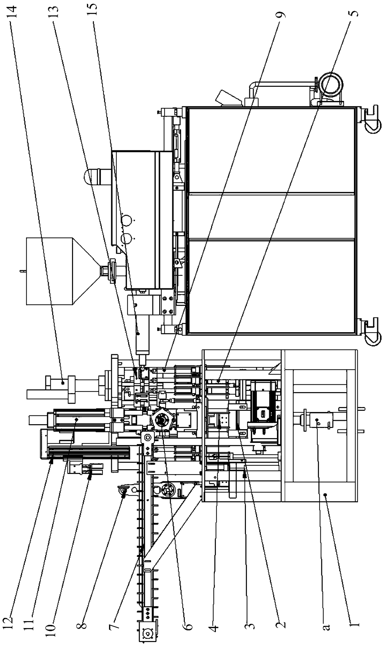
[0012] figure 1 It is a structural schematic diagram of the upper shoulder bowl compression molding type shoulder injection machine in the embodiment of the present invention.

[0013] like figure 1 As shown, the upper shoulder bowl compression molding type shoulder injection machine has: frame 1, water cooling system, vacuum system, splitter 2, outlet pipe ejection cylinder 3, inlet pipe ventilation cylinder 4, support positioning mechanism 5, inlet pipe rotary Wheel 6, Conveyor belt 7, Manipulator for turning out pipe 8, Mandrel for lower mold 9, Manipulator for lifting out pipe 10, Mechanism for pressing down pipe 11, Mechanism for lifting out pipe 12, Upper mold 13, Gas-liquid pressurization Cylinder 14 and extruding plastic mechanism 15.

[0014] The frame 1 has a...


PUM


Abstract

The invention provides an upper shoulder bowl compression molding type shoulder injection machine, which is characterized by comprising: a rack having a first layer, a second layer, a third layer and a fourth layer; a water cooling system; a vacuum system; a main motor connected to the water cooling system and the vacuum system; a divider connected to the main motor; a pipe outlet ejecting gas cylinder vertically arranged beside the divider; a pipe inlet ventilation gas cylinder connected to the divider; a supporting positioning mechanism connected to the divider and used for supporting the mold closing and positioning a soft pipe; a pipe inlet rotation wheel connected to the pipe inlet ventilation gas cylinder; a conveying belt connected to the pipe inlet rotation wheel; a pipe outlet rotation-out mechanical arm arranged beside the conveying belt; a mold discharging core rod connected to the divider; a pipe outlet lifting mechanical arm arranged above the conveying belt; a pipe inlet pressing mechanism arranged above the pipe inlet rotation wheel; a pipe outlet lifting mechanism connected to the pipe outlet lifting mechanical arm; a mold applying mold arranged above the pipe inlet rotation wheel; a gas-liquid pressurization cylinder connected to the mold applying mold; and a blow molding mechanism.

Description

technical field [0001] The invention relates to a positioning device, in particular to an upper shoulder bowl compression molding type shoulder injection machine. Background technique [0002] An existing hose shoulder injection machine is composed of a semi-automatic slide plate injection molding machine filling shoulder mold, manual intubation and extubation, high labor intensity, low production efficiency, poor safety performance, high machine use cost, and will generate a large amount of Plastic return. Another kind of hose shoulder injection machine is an automatic hose injection shoulder machine developed both at home and abroad. Its basic mechanism is a horizontal turntable type, which automatically spits out plastic, and punches downward after turning over the mandrel. There are many actions, and the failure rate of domestic machines is high, which is still immature. Although foreign machines have few failures, the cost of the machine is high, the price is high, the...

Claims


Application Information

Patent Timeline
Patent Type & Authority Patents(China)
IPC IPC(8): B29C45/06B29C45/14B29C45/73B29C45/57
CPCB29C45/06B29C45/14008B29C45/14065B29C45/14336B29C45/57B29C45/73
Inventor 田林樊学徐海华
Owner SHANGHAI JUXIN AUTOMATION EQUIP CO LTD
Why Eureka
Try Eureka