Optical fiber strain coefficient automatic calibration method

An optical fiber strain and automatic calibration technology, which is applied in the direction of optical devices, measuring devices, instruments, etc., can solve the problem of large errors in manual testing methods, difficulty in meeting the requirements for fast and accurate testing of optical fiber strain coefficients, and spending a lot of time and energy. question

Active Publication Date: 2017-03-08
THE 41ST INST OF CHINA ELECTRONICS TECH GRP
View PDF5 Cites 5 Cited by
  • Summary
  • Abstract
  • Description
  • Claims
  • Application Information

AI Technical Summary

Problems solved by technology

At present, the commonly used optical fiber gauge coefficient calibration methods are manual calibration methods, which apply strain to the optical fiber through devices such as equal-intensity beams and translation stages, manually find the strain position, and manually change the strain value to achieve the calibration of the optical fiber gauge coeffi

Method used


Image

  • Optical fiber strain coefficient automatic calibration method
  • Optical fiber strain coefficient automatic calibration method
  • Optical fiber strain coefficient automatic calibration method

Examples


Embodiment Construction

[0108] The present invention will be further described below in conjunction with the accompanying drawings and embodiments.

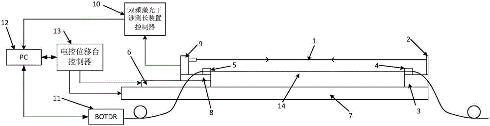
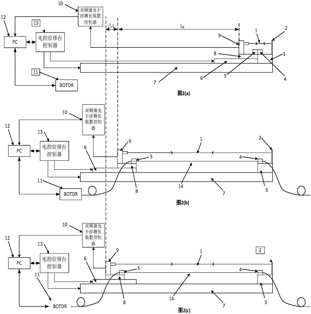
[0109] like figure 1 As shown, an automatic calibration device for optical fiber gage factor includes a first electronically controlled translation stage, namely the long-distance electronically controlled translation platform 7 in the figure, and a first clamp bearing platform, namely the right Fixture carrying platform 3, the first electronically controlled displacement platform is provided with a relatively movable second electrically controlled displacement platform, that is, the high-precision electronically controlled displacement platform 6 in the figure, and the second electrically controlled displacement platform is also provided with a high-precision electronically controlled displacement platform. The mobile platform 8 of the electronically controlled displacement stage, the mobile platform 8 of the high-precision electronically controlled di...


PUM


Abstract

The present invention discloses an optical fiber strain coefficient automatic calibration method. The method includes the following steps that: the length of an optical fiber strain region is inputted, a measured optical fiber is tensioned and is fixed between a first fixture and a second fixture according to a set distance; an optical fiber length and an optical fiber refractive index are inputted; a main control computer starts automatic calibration; a Brillouin optical time domain reflectometer is adopted to test optical fiber strain distribution so as to find out an optical fiber length corresponding to the optical fiber strain region; the Brillouin optical time domain reflectometer is adopted to test optical fiber strain distribution so as to find out an acting area length of the measured optical fiber; a calibration stepping distance is determined according to the acting area length of the measured optical fiber; the Brillouin optical time domain reflectometer is adopted to test optical fiber strain distribution so as to read Brillouin frequency shift data corresponding to the optical fiber length corresponding to the optical fiber strain region, and movement is carried out, and N times of testing is carried out, wherein N is a natural number greater than or equal to 1, the data array of the corresponding optical fiber length and a Brillouin frequency shift data array corresponding to the optical fiber length are obtained; and the data are linearly fitted, so that the strain coefficient FCS of the measured optical fiber can be obtained.

Description

technical field [0001] The invention relates to an automatic calibration method for optical fiber strain coefficient. Background technique [0002] The optical fiber strain distribution tester calculates the strain distribution of the optical fiber by measuring the Brillouin frequency shift distribution of the backward Brillouin scattered light in the optical fiber. The pulsed light is incident from one end of the optical fiber at a certain frequency, and the incident pulsed light and the phonon Brillouin scattering occurs after the interaction occurs, and the back Brillouin scattered light returns to the incident end along the original path of the fiber. Since there is a linear relationship between the frequency shift of the Brillouin scattered light in the fiber and the axial strain and temperature of the fiber, the strain distribution in the fiber can be calculated by measuring the Brillouin scattered frequency shift distribution of the fiber. Brillouin optical time doma...

Claims


Application Information

Patent Timeline
IPC IPC(8): G01B11/16
CPCG01B11/16
Inventor 李立功袁明闫继送吴寅初于文林杨鹏郭洪龙毕宗义刘雷于文潇
Owner THE 41ST INST OF CHINA ELECTRONICS TECH GRP
Why Eureka
Try Eureka