A stray light suppression method for all-day high-precision starlight refraction navigation

A technology of star light refraction and stray light, applied in astronomical navigation and other directions, can solve the problems of large index difference, excessive cost, serious problems, etc., and achieve the effect of correct determination method, high result accuracy, and guaranteed accuracy.

Inactive Publication Date: 2019-04-09
CHINA ACADEMY OF SPACE TECHNOLOGY
View PDF5 Cites 0 Cited by
  • Summary
  • Abstract
  • Description
  • Claims
  • Application Information

AI Technical Summary

Problems solved by technology

One is the detection of exoplanets, that is, the problem of observing dark point sources around bright point sources. In order to effectively extract dark targets, it is necessary to reduce the influence of stray light from bright targets on dark targets. Generally, special filters or large telescopes are used. However, the bright earth in the field of view is the bright surface source during starlight refraction navigation, and the distribution of refracting stars is changing in real time. The method of using special filters cannot guarantee the effective observation field of refracting stars, but will make Stray light in some areas is more serious, and the cost of using large telescopes on satellites to realize starlight refraction navigation will be too high; the other is coronal detection. In order to achieve clear imaging observations of the corona, the coronagraph stray light suppression level Generally at 1.1R ⊙ (R ⊙ is the radius of the sun) is 10 of the solar photosphere radiation -6 times, at 2.5R ⊙ 10 of the solar photosphere radiation -8 times, although starlight refraction navigation and coronal observation are both faced with stray light interference from bright surface sources, the indicators of the two are quite different. Therefore, the stray light suppression method of starlight refraction navigation cannot be generalized with the coronagraph suppression method. Especially the problem of diffracted stray light caused by bright surface sources in the optical system. For example, the problem of diffracted stray light of the bright sun image can not be considered if the coronagraph of the inner cover is used, and the refracted star is very close to the edge of the earth during starlight refraction navigation. The mask system needs to consider the diffraction stray light problem of the bright earth image

Method used


Image

  • A stray light suppression method for all-day high-precision starlight refraction navigation
  • A stray light suppression method for all-day high-precision starlight refraction navigation
  • A stray light suppression method for all-day high-precision starlight refraction navigation

Examples


Embodiment Construction

[0038] The present invention will be described in further detail below in conjunction with accompanying drawing and example.

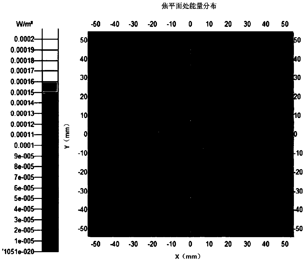
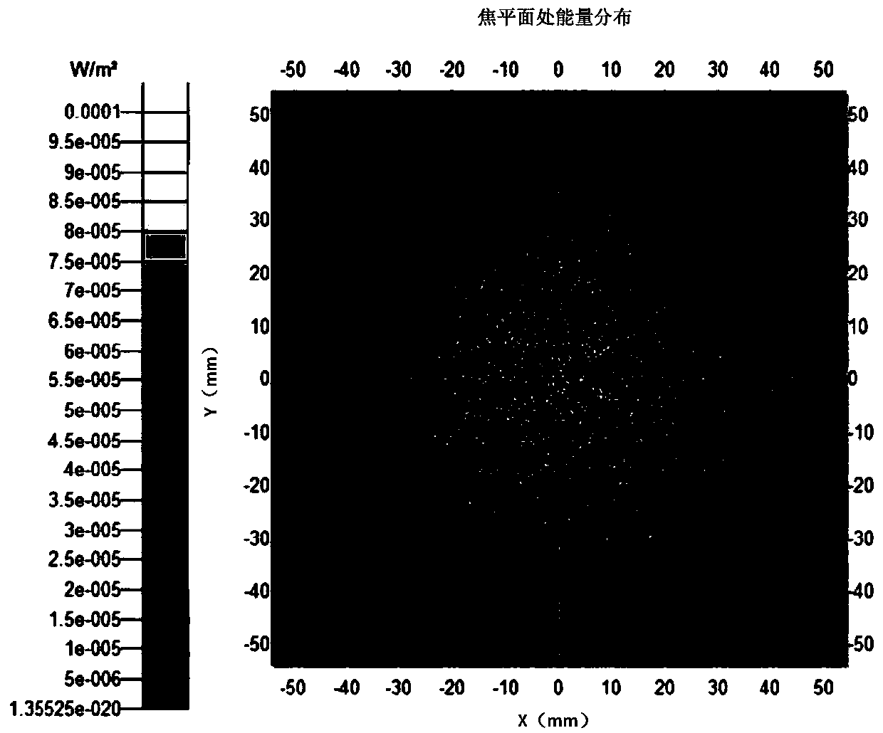
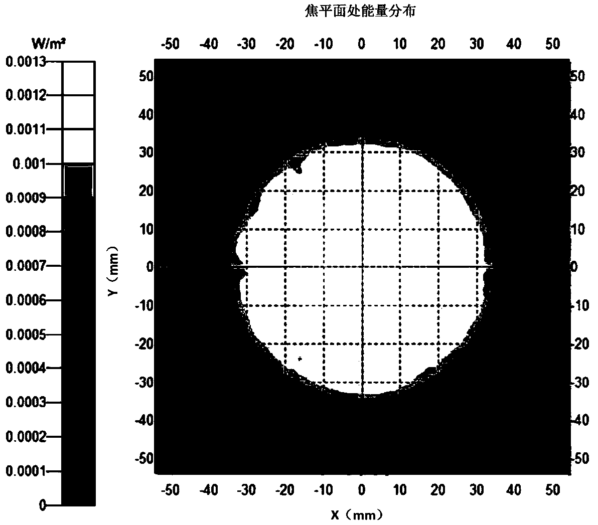
[0039] An all-time high-precision starlight refraction navigation stray light suppression method provided by the present invention comprises the following steps in sequence: according to the starlight refraction navigation observation environment and the starlight refraction sensor index, the type of stray light of the starlight refraction sensor is determined, and the stray light is determined according to the intensity. Weak grades are divided into three grades; stray light intensity and suppression effects at all levels are determined sequentially. Firstly, the starlight refraction sensor model is constructed, the starlight refraction navigation simulation observation environment is set up to carry out simulation analysis, or calculation and analysis are carried out according to the principle formula, etc., to obtain Calculate the intensity of stray ...


PUM


Abstract

The invention relates to an all-time high-accuracy stellar refraction navigation stray light inhibiting method. The method comprises steps as follows: 1) stray light is divided into three classes; 2) primary stray light is processed, the intensity of the primary stray light is determined, and the primary stray light is inhibited; 3) secondary stray light is processed, the intensity of the secondary stray light is determined, and the secondary stray light is inhibited. The adopted internally occulted stray light inhibiting technology is effective and facilitates miniaturization design of a stellar refraction sensor; a method for determining the intensity of stray light is right and high in result accuracy; different classes of stray light intensity and the inhibiting effects are determined on the basis of a stray light generation principle in combination with different optical analysis tools, the accuracy of the method for determining different classes of stray light is checked, and the effectiveness and the high accuracy of results are ensured; technical support is provided for inhibition of stray light in a very close distance from a bright surface source under stellar refraction navigation and other conditions.

Description

technical field [0001] The invention relates to a method for suppressing stray light of an optical sensor, in particular to a method for suppressing stray light around the earth image when the earth illuminated by the sun enters the field of view during starlight refraction navigation. Background technique [0002] Starlight refraction navigation is to use the optical sensor installed on the satellite to measure the refraction of starlight when it passes through the atmosphere (20-80km) at the edge of the earth, indirectly obtain horizon information, and obtain the position of the satellite in the geocentric coordinate system, so as to determine Method of satellite orbit. When a high-orbit satellite uses a starlight refraction sensor with a large field of view to carry out all-day high-precision starlight refraction navigation, in order to obtain enough refraction stars, it will be faced with the high-precision extraction of the atmosphere at the edge of the earth ( 20-80km...

Claims


Application Information

Patent Timeline
Patent Type & Authority Patents(China)
IPC IPC(8): G01C21/02
CPCG01C21/02
Inventor 林亲李志李怀锋
Owner CHINA ACADEMY OF SPACE TECHNOLOGY
Why Eureka
Try Eureka