Electro-optic Arbitrary Waveform Generator Based on Graphene Grating Microfiber
What is AI technical title?
AI technical title is built by PatSnap AI team. It summarizes the technical point description of the patent document.
An arbitrary waveform and graphene technology, applied in instruments, optics, nonlinear optics, etc., can solve problems such as difficult to manufacture and expensive, and achieve the effect of low transmission loss and easy manufacture
Active Publication Date: 2019-07-05
BEIJING JIAOTONG UNIV
View PDF5 Cites 0 Cited by
Summary
Abstract
Description
Claims
Application Information
AI Technical Summary
This helps you quickly interpret patents by identifying the three key elements:
Problems solved by technology
Method used
Benefits of technology
Problems solved by technology
[0011] It should be noted that the existing modulators all use single-point modulation in space, so that the speed of the modulated signal generated is equal to the speed of the modulated signal. When it is necessary to load an ultra-high frequency signal in the carrier, an ultra-high speed is required. The modulation signal of the modulation signal, and the high-speed circuit that produces the ultra-fast electrical signal and the optical system that produces the optical pulse sequence of the ultra-high repetition frequency are difficult to make, and the price is expensive
Method used
Image
Click on the blue label to locate the original text in one second.
Reading with bidirectional positioning of images and text.
Examples
Embodiment 1
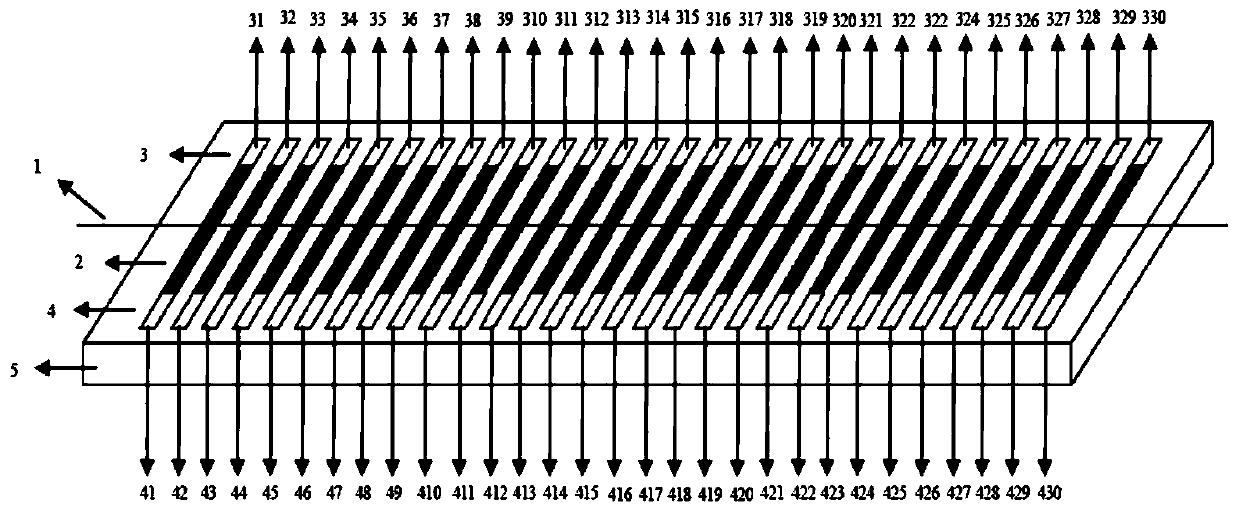
[0086] The arbitrary waveform generator includes a microfiber 1, a graphene grid layer 2, a positive electrode array 3 (positive electrodes 31, 32, 33, 34, 35, 36, 37, 38, 39, 310, 311, 312, 313, 315 , 316, 317, 318, 319, 320, 321, 322, 323, 324, 325, 326, 327, 328, 329, 330), negative electrode array 4 (negative electrode 41, 42, 43, 44, 45, 46 , 47, 48, 49, 410, 411, 412, 413, 414, 415, 416, 417, 418, 419, 420, 421, 422, 423, 424, 425, 426, 427, 428, 429, 430), Flat base 5( figure 1 ). The combination method is as follows: the graphene grid layer 2 is placed on the flat substrate 5, and the microfiber 1 is placed on the graphene grid layer 2. The diameter of the fine optical fiber 1 is 8 μm, the unit length of the graphene grid layer 2 is 300 μm, the distance between adjacent units is 280 μm, the number of units is 30, and the size of the entire flat substrate 5 is 18 mm×1 mm. The number of graphene gate layer 2 used is 1. The carrier wave is introduced from one end of t...
Embodiment 2
[0088] The arbitrary waveform generator includes a microfiber 1, a graphene grid layer 2, a positive electrode array 3 (positive electrodes 31, 32, 33, 34, 35, 36, 37, 38, 39, 310, 311, 312, 313, 315 , 316, 317, 318, 319, 320, 321, 322, 323, 324, 325, 326, 327, 328, 329, 330), negative electrode array 4 (negative electrode 41, 42, 43, 44, 45, 46 , 47, 48, 49, 410, 411, 412, 413, 414, 415, 416, 417, 418, 419, 420, 421, 422, 423, 424, 425, 426, 427, 428, 429, 430), Flat base 5( figure 1 ). The combination method is as follows: the graphene grid layer 2 is placed on the flat substrate 5, and the microfiber 1 is placed on the graphene grid layer 2. The diameter of the fine optical fiber 1 is 5 μm, the unit length of the graphene grid layer 2 is 120 μm, the distance between adjacent units is 110 μm, the number of units is 30, and the size of the entire flat substrate 5 is 7 mm×1 mm. The number of graphene gate layers 2 used is four. The carrier wave is introduced from one end o...
PUM
Property
Measurement
Unit
diameter
aaaaa
aaaaa
length
aaaaa
aaaaa
diameter
aaaaa
aaaaa
Abstract
The invention relates to an electro-optical random waveform generator based on micro-fine optical fibers of a graphenegrating layer. The electro-optical random waveform generator comprises the micro-fine optical fibers, the graphenegrating layer, a positive-electrode array, a negative-electrode array and a flat-plate substrate, wherein the graphenegrating layer is arranged on the flat-plate substrate; the micro-fine optical fibers are arranged on the graphene grating layer; the positive-electrode array comprises a plurality of positive electrodes; the negative-electrode array comprises a plurality of negative electrodes; and all the positive electrodes of the positive-electrode array and all the negative electrodes of the negative-electrode array are respectively connected with the two ends of all units of the graphene grating layer. The electro-optical random waveform generator has the advantages that the needed waveform is edited into a space-electric signal array changing along with the time, and the space-electric signal array changing along with the time is applied to the two ends of all units of the graphene grating layer; the space-electric signal array generated by the electrode array is changed by lower frequency; and the generator can generate any needed waveform accurately.
Description
technical field [0001] The invention belongs to the field of optical fiber devices for communication, and in particular relates to an electro-optic arbitrary waveform generator based on a graphene grid layer microfiber. Background technique [0002] Arbitrary waveform optical pulses (OAWG) can meet the requirements of the next generation network for ultra-high-speed transmission rates and ultra-wide bandwidth: OAWG can generate broadbandmicrowave signals, such as Gaussian signals suitable for communication and waveforms with high energy efficiency; OAWG can provide complex All-optical vector modulation formats, such as QAM, QPSK, DPSK, DSB-SC, etc., improve transmission spectrum efficiency; OAWG can perform dispersion compensation on received signals to improve signal quality; OAWG can perform terahertz signal synthesis to adapt to ultra-high-speed communication systems; OAWG is used to generate optical labels in the all-optical packet network; OAWG can also generate arbitr...
Claims
Application Information
Patent Timeline
Application Date:The date an application was filed.
Publication Date:The date a patent or application was officially published.
First Publication Date:The earliest publication date of a patent with the same application number.
Issue Date:Publication date of the patent grant document.
PCT Entry Date:The Entry date of PCT National Phase.
Estimated Expiry Date:The statutory expiry date of a patent right according to the Patent Law, and it is the longest term of protection that the patent right can achieve without the termination of the patent right due to other reasons(Term extension factor has been taken into account ).
Invalid Date:Actual expiry date is based on effective date or publication date of legal transaction data of invalid patent.

