Electro-optical arbitrary waveform generator based on graphene grid silicon waveguide
An arbitrary waveform and silicon waveguide technology, applied in the direction of instruments, optics, nonlinear optics, etc., can solve the problems that cannot fully meet the needs of modulation speed, and achieve the effects of avoiding high loss, wide working bandwidth, and reducing costs
- Summary
- Abstract
- Description
- Claims
- Application Information
AI Technical Summary
Problems solved by technology
Method used
Image
Examples
Embodiment 1
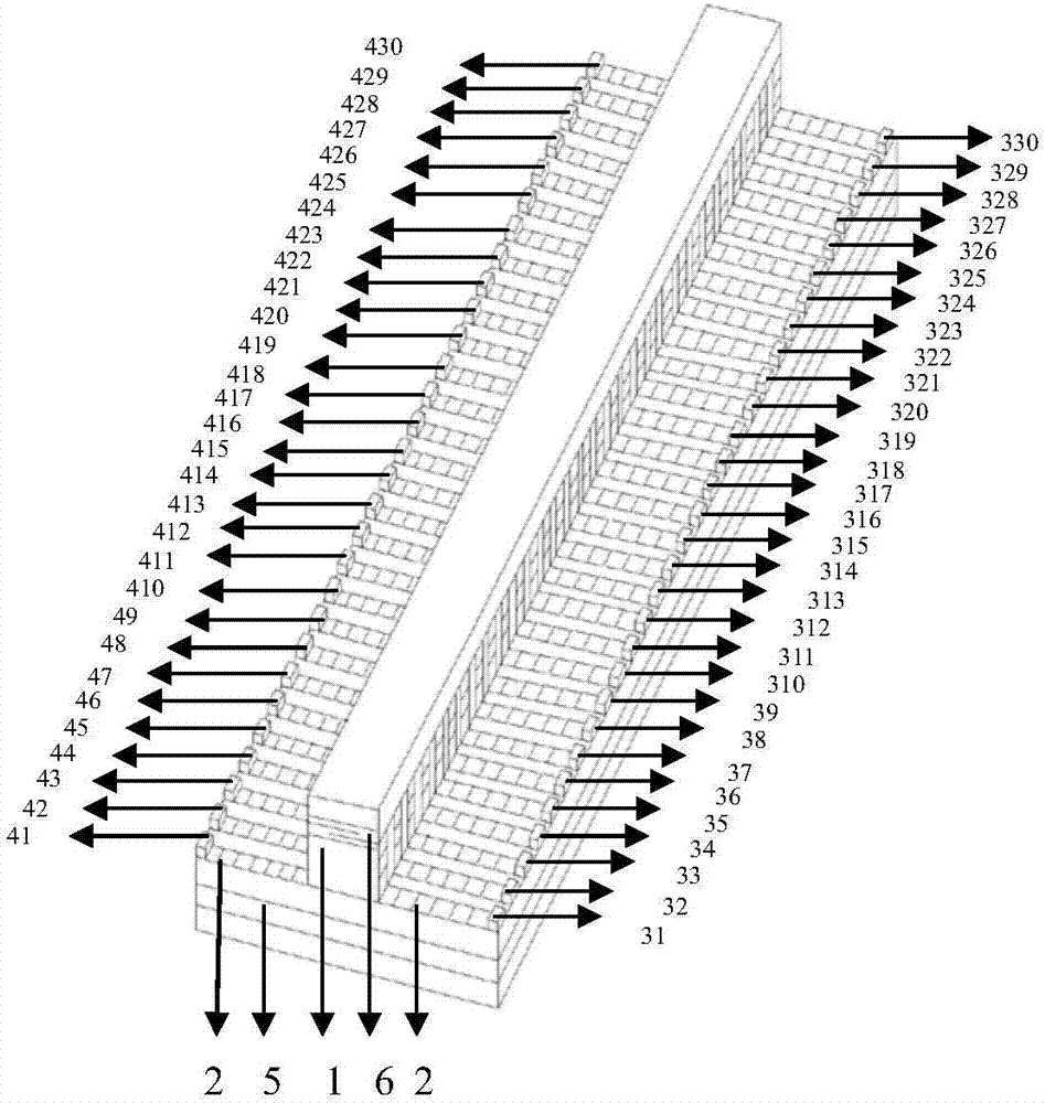
[0063] The arbitrary waveform generator comprises a ridge silicon waveguide 1, a graphene grid layer 2, a positive electrode array 3 (positive electrode units 31, 32, 33, 34, 35, 36, 37, 38, 39, 310, 311, 312, 313, 315, 316, 317, 318, 319, 320, 321, 322, 323, 324, 325, 326, 327, 328, 329, 330), negative electrode array 4 (negative electrode unit 41, 42, 43, 44 ,45,46,47,48,49,410,411,412,413,414,415,416,417,418,419,420,421,422,423,424,425,426,427,428,429 , 430), flat substrate 5, hBN layer 6 ( figure 1 ). The combination method is: the ridge waveguide modulator structure uses silicon-on-insulator SOI as the base, several layers of graphene and hBN layers are inserted into the middle of the ridge waveguide, a layer of polysilicon is evaporated on the top layer, and the positive and negative electrode arrays are on both sides of the silicon waveguide and graphite Alkene layers are connected to form a modulation unit, and multiple unit modulators are arranged repeatedly to form...
Embodiment 2
[0065] The arbitrary waveform generator comprises a ridge silicon waveguide 1, a graphene grid layer 2, a positive electrode array 3 (positive electrode units 31, 32, 33, 34, 35, 36, 37, 38, 39, 310, 311, 312, 313, 315, 316, 317, 318, 319, 320, 321, 322, 323, 324, 325, 326, 327, 328, 329, 330), negative electrode array 4 (negative electrode unit 41, 42, 43, 44 ,45,46,47,48,49,410,411,412,413,414,415,416,417,418,419,420,421,422,423,424,425,426,427,428,429 , 430), flat substrate 5, hBN layer 6 ( figure 1 ). The combination method is: the ridge waveguide modulator structure uses silicon-on-insulator SOI as the base, several layers of graphene and hBN layers are inserted into the middle of the ridge waveguide, a layer of polysilicon is evaporated on the top layer, and the positive and negative electrode arrays are on both sides of the silicon waveguide and graphite Alkene layers are connected to form a modulation unit, and multiple unit modulators are arranged repeatedly to form...
PUM
| Property | Measurement | Unit |
|---|---|---|
| height | aaaaa | aaaaa |
| thickness | aaaaa | aaaaa |
Abstract
Description
Claims
Application Information
 - R&D
- Intellectual Property
- Life Sciences
- Materials
- Tech Scout
- Unparalleled Data Quality
- Higher Quality Content
- 60% Fewer Hallucinations
Browse by: Latest US Patents, China's latest patents, Technical Efficacy Thesaurus, Application Domain, Technology Topic, Popular Technical Reports.
© 2025 PatSnap. All rights reserved.Legal|Privacy policy|Modern Slavery Act Transparency Statement|Sitemap|About US| Contact US: help@patsnap.com


