Stress relaxation effect considered method and device for evaluating creep-fatigue life of high temperature component

A technology for stress relaxation and high temperature components, which is applied in the field of creep fatigue life evaluation methods and evaluation devices for high temperature components, which can solve the problems of complex calculation of multi-axis correction factors, not recommended, and inability to guarantee stress history.

Active Publication Date: 2017-03-08
AECC COMML AIRCRAFT ENGINE CO LTD
View PDF5 Cites 15 Cited by
  • Summary
  • Abstract
  • Description
  • Claims
  • Application Information

AI Technical Summary

Problems solved by technology

Compared with the first method, this method greatly simplifies the calculation workload, but the algorithm using empirical formulas makes the fitting error larger, and more importantly, this method cannot guarantee that the stress history obtained by simulation is conservative (see literature : Journal of Mechanical Strength, 2001,23(1):004.), it is not recommended to use in actual engine life prediction
In addition, when using the equal strain relaxation model for approximate calculation, it is often necessary to consider the multiaxial load of the actual component through the multiaxial correction factor. Since the stress on the component is constantly changing during the service process, the multiaxial stress state is also constantly changing. The calculation of the multi-axis correction factor itself is very complicated (see patents: CN 103761365B and CN 103712865A)
In addition, the stress relaxation formula based on the uniaxial equi-strain relaxation model is more suitable for the stress relaxation process under constant load, and cannot be directly applied to the multi-state point variable load situation of the aero-engine.

Method used


Image

  • Stress relaxation effect considered method and device for evaluating creep-fatigue life of high temperature component
  • Stress relaxation effect considered method and device for evaluating creep-fatigue life of high temperature component
  • Stress relaxation effect considered method and device for evaluating creep-fatigue life of high temperature component

Examples


Embodiment Construction

[0048] The present invention will be described in detail below in conjunction with the accompanying drawings and specific embodiments. Note that the aspects described below in conjunction with the drawings and specific embodiments are only exemplary, and should not be construed as limiting the protection scope of the present invention.

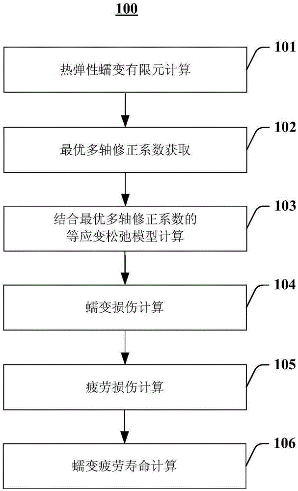
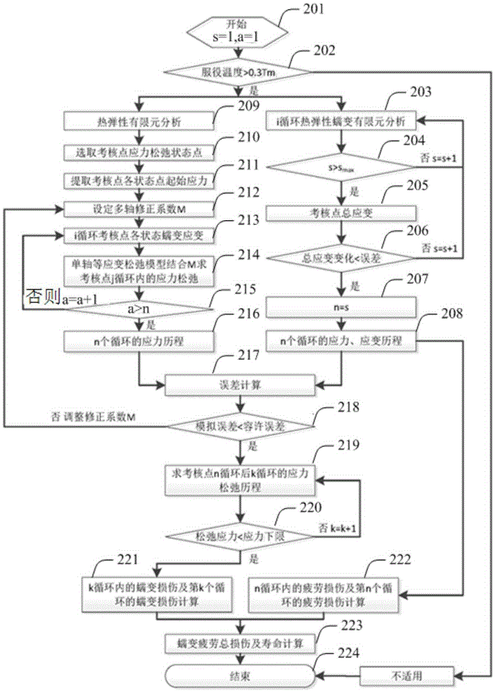
[0049] In the present invention, a calculation strategy combining finite element calculation and equal strain relaxation model is adopted. First, a certain number of load cycles are calculated by using the thermoelastic creep finite element until the total strain of each state point at the examination point remains basically unchanged. At this time, use the uniaxial equal strain relaxation model combined with the multiaxial correction coefficient M to calculate the same number of load cycles. By continuously adjusting the multiaxial correction coefficient M, the uniaxial equal strain relaxation model combined with the multiaxial correction coe...


PUM


Abstract

The invention provides a method for evaluating a creep-fatigue life. The method comprises the steps of performing finite element calculation till a total strain for each state point of an examination point is stable, wherein a load cycle when the total strain is stable is the cycle n; based on a monoaxial equal strain relaxation model and in combination with a multiaxial correction coefficient M, calculating a stress of the examination point till the cycle n, wherein the M is adjusted continuously so that a calculated stress course is consistent with the stress course calculated out in the step (a) to obtain the optimal multiaxial correction coefficient M; calculating a stress relaxation course of the examination point after n cycles by employing the optimal multiaxial correction coefficient M and based on the monoaxial equal strain relaxation model till stress relaxation for each state point of the examination point is stable, wherein the load cycle when the stress relaxation is stable is the cycle k; calculating a creep damage in previous k load cycles and the creep damage for the load cycle k; calculating a fatigue damage in previous n load cycles and the fatigue damage for the load cycle n; and thereby calculating the creep-fatigue life.

Description

technical field [0001] The invention relates to a life evaluation technology of high-temperature parts of an aero-engine, in particular to a creep fatigue life evaluation method and an evaluation device of a high-temperature part considering stress relaxation with less calculation amount and high precision. Background technique [0002] During the service process, the hot-end parts of the aero-engine bear not only the fatigue damage caused by the landing cycle, but also the creep damage caused by the continuous stress and temperature. The total damage is the combination of fatigue, creep and the interaction between them. Caused. With the continuous increase of the inlet temperature of the high-performance aero-engine turbine, the service temperature of the hot-end components continues to increase, which makes the proportion of damage caused by the interaction of creep and creep fatigue also increase. On the other hand, due to the existence of stress relaxation caused by cre...

Claims


Application Information

Patent Timeline
IPC IPC(8): G06F17/50
Inventor 高靖云张成成侯乃先任远李颖
Owner AECC COMML AIRCRAFT ENGINE CO LTD
Why Eureka
Try Eureka