

Sealing method of heat-conducting component
A technology for thermally conductive components and components, which is applied in the direction of semiconductor/solid-state device components, semiconductor devices, electrical components, etc., and can solve problems such as circuit short circuit and leakage
- Summary
- Abstract
- Description
- Claims
- Application Information
AI Technical Summary
Problems solved by technology
Method used
Image

Examples
Embodiment 1
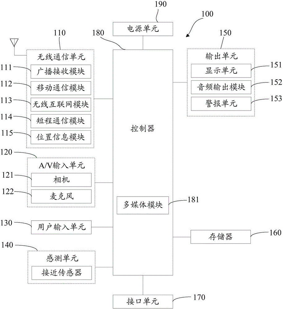
[0082] An embodiment of the present invention proposes a mobile terminal, a schematic diagram of a hardware structure of the mobile terminal is shown in figure 1 shown.
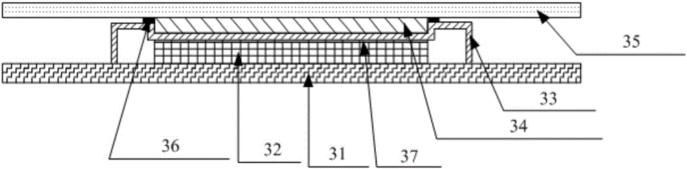
[0083] In this example, if image 3 As shown, the mobile terminal includes:
[0084] PCB 31;
[0085] A chip 32 is fixed on the PCB 31, and the chip 32 can generate heat during operation;
[0086] The shielding cover 33 is fixed to the PCB 31, that is, it is arranged on the PCB 31 and surrounds the chip 32. Part of the shielding cover 33 forms a groove above the chip 32, and the groove The bottom is in contact with the upper surface of the chip 32;
[0087] The first heat conduction component 34 is arranged in the groove; the first heat conduction component 34 is a metal phase change material;
[0088] The heat-conducting middle frame 35 is connected with the shield cover 33 to seal the groove into a sealed space; wherein,
[0089] After the middle frame 35 is connected to the shielding case 33, the fir...
Embodiment 2
[0120] An embodiment of the present invention proposes a mobile terminal, a schematic diagram of a hardware structure of the mobile terminal is shown in figure 1 shown.
[0121] In this example, if image 3 As shown, the mobile terminal includes:
[0122] PCB 31;
[0123] A chip 32 is fixed on the PCB 31, and the chip 32 can generate heat during operation;
[0124] The shielding cover 33 is fixed to the PCB 31, that is, it is arranged on the PCB 31 and surrounds the chip 32. Part of the shielding cover 33 forms a groove above the chip 32, and the groove The bottom is in contact with the upper surface of the chip 32;
[0125] The first heat conduction component 34 is arranged in the groove; the first heat conduction component 34 is a metal phase change material;
[0126] The heat-conducting middle frame 35 is connected with the shield cover 33 to seal the groove into a sealed space; wherein,
[0127] After the middle frame 35 is connected to the shielding case 33, the fir...
Embodiment 3
[0162] Based on the mobile terminal provided in Embodiment 1 of the present invention, this embodiment provides a method for sealing heat-conducting components, such as Figure 4 As shown, the method includes the following steps:
[0163] Step 401: Fix the shielding cover provided with the groove on the PCB on which the chip is fixed, and surround the chip;
[0164] Here, the chip can generate heat during operation.
[0165] Part of the shielding cover forms the groove above the chip, and the bottom of the groove is in contact with the upper surface of the chip.
[0166] In one embodiment, the method may also include:
[0167] The chip is fixed on the PCB by patching.
[0168] Wherein, in actual application, the most commonly used method of mounting is: soldering the chip on the PCB by using solder strips (wires) or the like.
[0169] Correspondingly, the shielding case can be fixed on the PCB by means of patches.
[0170] In one embodiment, the method may also include: ...
PUM
 Abstract
Description
Claims
Application Information