A multi-time scale microgrid voltage and reactive power optimization control method

A voltage and reactive power optimization, multi-time scale technology, applied in the field of microgrid, can solve the problems of inability to guarantee the quality of power supply voltage for important loads, inability to make full use of reactive power regulation capabilities, and long computing time.

Active Publication Date: 2019-01-15
HEFEI UNIV OF TECH
View PDF4 Cites 0 Cited by
  • Summary
  • Abstract
  • Description
  • Claims
  • Application Information

AI Technical Summary

Problems solved by technology

The main disadvantages of the two-stage voltage control consisting of secondary voltage control and local DG control are: 1) It is impossible to guarantee the voltage amplitude of other nodes except the key node; DG's reactive power adjustment capability; 3) It does not contribute much to reactive power equal sharing control, and cannot solve the problem of reactive power circulation between DGs
In order to solve the above problems, there are also literatures that change the secondary voltage control based on PI into a multi-node voltage optimization control method, but the calculation time of the optimization control is long, the real-time and dynamic performance of the voltage control is poor, and the power supply of important loads cannot be guaranteed. voltage quality

Method used


Image

  • A multi-time scale microgrid voltage and reactive power optimization control method
  • A multi-time scale microgrid voltage and reactive power optimization control method
  • A multi-time scale microgrid voltage and reactive power optimization control method

Examples


Embodiment 1

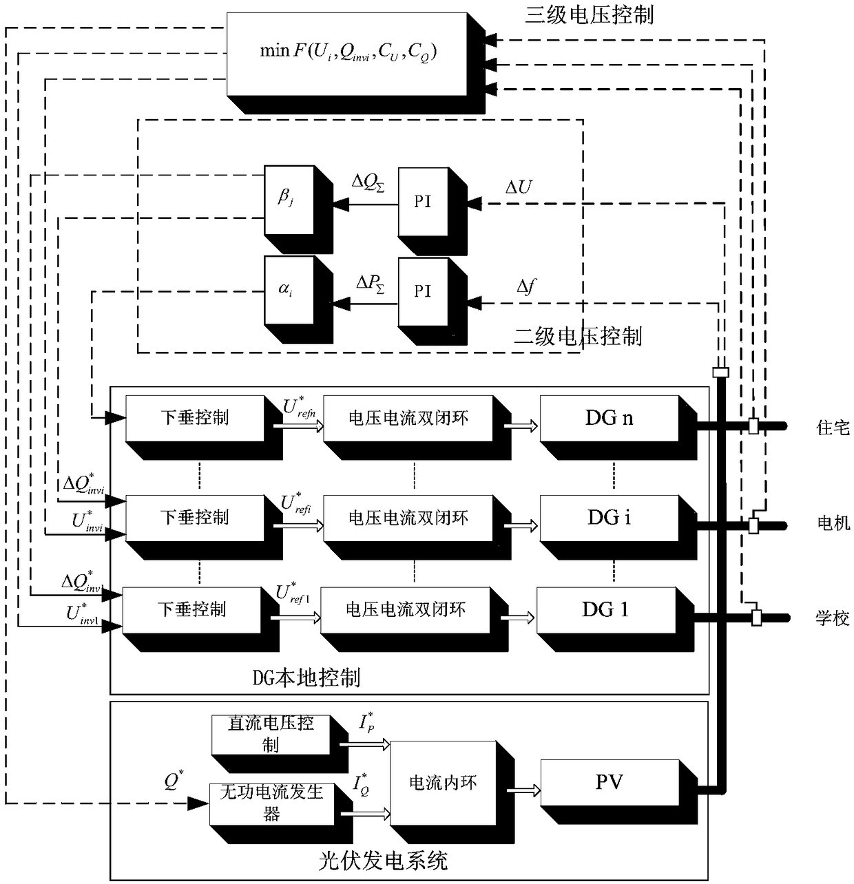
[0037] figure 1 It is a structural schematic diagram of the present invention, figure 1 The first-level voltage control layer is DG local control; the second-level voltage control layer is MGCC voltage control. In this control layer, the unplanned reactive power is calculated by inputting the voltage deviation of key bus nodes into the PI regulator, and then the The unplanned reactive power is distributed to each voltage-regulating inverter according to the distribution coefficient to change its voltage regulation characteristics and maintain the voltage level of key bus nodes; the third-level voltage control layer is EMS voltage control, which makes full use of renewable energy The reactive power regulation capability of power generation is aimed at controlling the voltage level of multiple nodes in the microgrid, suppressing reactive power circulation, and improving active power and reactive power margins, and performs global voltage control. In addition, the secondary freq...


PUM


Abstract

The invention discloses a multi-time scale microgrid voltage reactive power optimization control method. A DG (Distributed Generator) primary voltage control layer, a MGCC (Microgrid Central Controller) secondary voltage control layer and an EMS (Energy Manage System) tertiary voltage control layer are included. In the tertiary voltage control layer, voltage optimization coordination control which is composed of three parts of an objective function, an equality constraint and an inequality constraint is set. The multi-time scale microgrid voltage reactive power optimization control method provided by the invention comprehensively uses advantages of quickness of primary voltage control, accuracy of secondary voltage single-bus control and global optimization scheduling of tertiary voltage control, the reactive power regulation ability of the distributed generator unit existing in the microgrid is made full use of, the multi-bus node voltage level is maintained, reactive power circulation is suppressed, reactive power optimization distribution is realized, as much as reactive power margin and active power margin is provided for the microgrid, the system stability is improved, and the investment of system reactive power compensation equipment is reduced.

Description

technical field [0001] The invention relates to a microgrid technology in the field of new energy power generation in a power system, in particular to a multi-time scale microgrid voltage and reactive power optimization control method. Background technique [0002] Microgrid is one of the research hotspots in the field of distributed power generation. Drawing on the concept of hierarchical control of power systems, microgrid control is usually divided into three layers: the first layer is the local control of the distributed generation unit DG (Distributed Generator), including PQ control, droop control, mode switching, etc.; the second layer is the central control MGCC (Microgrid Central Controller), the main functions are to restore the system voltage and frequency in the island operation mode, the power flow control of the tie line in the network mode, pre-synchronization, island detection, etc.; the third layer is the energy management system EMS (Energy Manage System). ...

Claims


Application Information

Patent Timeline
Patent Type & Authority Patents(China)
IPC IPC(8): H02J3/50
CPCY02P80/14
Inventor 杨向真杜燕苏建徽施永邓弯弯
Owner HEFEI UNIV OF TECH
Why Eureka
Try Eureka