
A micro-energy grid system and a voltage regulating control method thereof

A voltage regulation control and micro-energy technology, applied in the field of electric power, can solve the problems of node voltage fluctuation, difficult to control, affecting the quality of power supply, etc., to achieve high quality and improve reliability.

Active Publication Date: 2018-12-18
CHINA ELECTRIC POWER RES INST +2
View PDF1 Cites 2 Cited by
  • Summary
  • Abstract
  • Description
  • Claims
  • Application Information

AI Technical Summary

Problems solved by technology

[0003] However, wind energy and solar energy are primary energy sources, which cannot be stored, and are easily affected by natural climate, and have strong random fluctuations, which determine the randomness of their power generation , intermittent, difficult to control
In particular, when the distributed power generation and the power distribution system are connected to the grid, many new problems will be caused in terms of power quality, system stability, voltage stability, reliability, and economy.
For example, due to the sudden change of the load in the micro energy network, the power generation and the load power will not match. These factors will cause the node voltage to fluctuate and affect the quality of power supply.

Method used


Image

  • A micro-energy grid system and a voltage regulating control method thereof
  • A micro-energy grid system and a voltage regulating control method thereof
  • A micro-energy grid system and a voltage regulating control method thereof

Examples


Embodiment 1

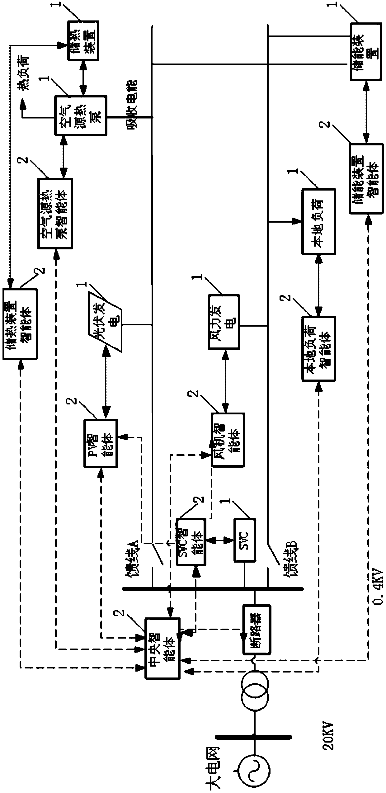
[0062] The invention provides a micro-energy network system, including: an execution device and a controller;

[0063] The controller collects the original electrical parameters of the execution equipment and adjusts the electrical parameters, and performs one-stage voltage regulation control on the execution equipment according to the original electrical parameters to stabilize the voltage of the micro energy network, and performs two-stage voltage regulation control on the execution equipment according to the adjusted electrical parameters , so that the voltage of the micro energy grid reaches the rated voltage;

[0064] Among them, the original electrical parameters are the electrical parameters collected before the first-level voltage regulation control; the adjusted electrical parameters are the electrical parameters collected after the first-level voltage regulation control.

[0065] What needs to be pointed out here is that after the first-level voltage regulation contr...

Embodiment 2

[0091] Based on the same inventive idea, the present invention also provides a voltage regulation control method for a micro-energy grid system. The flow chart of the method is shown in Figure 4 shown, including:

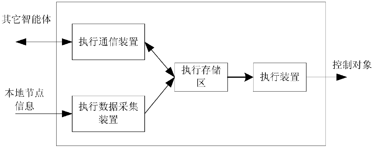
[0092] Step 1: The controller collects the original electrical parameters of the execution equipment;

[0093] Step 2: Perform primary voltage regulation control based on the original electrical parameters to stabilize the voltage of the micro energy grid;

[0094] Step 3: Perform secondary voltage regulation control according to the collected and adjusted electrical parameters, so that the voltage of the micro energy grid reaches the rated voltage;

[0095] Wherein, the original electrical parameters are electrical parameters collected before the first-level voltage regulation control; the adjusted electrical parameters are electrical parameters collected after the first-level voltage regulation control.

[0096] Specifically, a voltage regulation control method...

Embodiment 3

[0117] A specific embodiment of a voltage regulation control method for a micro energy grid system is given below.

[0118] In this example, the rated voltage U 0 = 220V, which is the rated voltage of the micro-energy network; the node frequency f of the distributed power source and the local load in the collected micro-energy network i , node voltage U i and rated reactive power Q 0,i ,As shown in Table 1:

[0119] Table 1

[0120]

[0121] The specific pressure regulation control process is as follows:

[0122] Step 201: Collect the original electrical parameters of the micro energy network, the original electrical parameters include: the node voltage of the distributed power supply, the node voltage of the static var compensator, the voltage of the energy storage device, the voltage of the heat storage device and the voltage of the local load , power and reactive power.

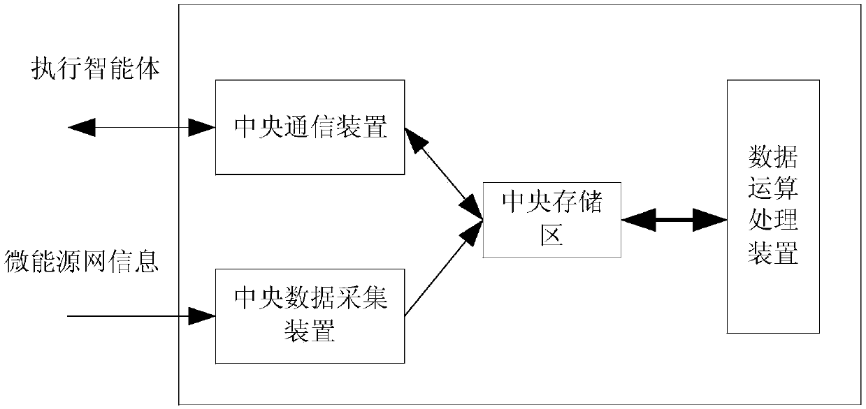
[0123] Step 202: According to the original electrical parameters, the central agent analyzes t...


PUM


Abstract

The invention provides a micro-energy grid system and a voltage regulating control method thereof, the system comprising: an execution device and a controller; The controller collects the original electrical parameters of the executing equipment, and controls the voltage of the executing equipment according to the original electrical parameters to perform primary voltage regulation control to stabilize the voltage of the micro-energy grid, and controls the voltage of the executing equipment according to the collected adjusted electrical parameters to perform secondyar voltage regulation control to make the voltage of the micro-energy grid reach the rated voltage. According to the collected electrical parameters of the micro-energy network, the voltage of the micro-energy grid is stabilizedby primary voltage regulation control, The voltage of the micro-energy grid can reach the rated voltage by using secondary voltage regulation control, which can adapt to the characteristics of load change and distributed renewable energy fluctuation, make full use of the reactive power capacity of the renewable energy, ensure the high quality of the output electric energy of the micro-energy grid, support the safety and stable operation of the distribution network, and improve the reliability of the distribution network.

Description

technical field [0001] The invention belongs to the technical field of electric power, and in particular relates to a micro energy network system and a voltage regulation control method thereof. Background technique [0002] With the gradual exhaustion of conventional energy and the increasing environmental pollution, the development of renewable energy has entered people's field of vision. The micro-energy grid with renewable energy as the core has been developed. As a supplement to the traditional power supply form, the micro-energy grid has the advantages of flexibility, wide application range, and low emission of pollutants, and can meet the needs of load growth, reduce environmental pollution, and improve energy efficiency. Comprehensive utilization rate of energy. Distributed power sources in the micro-energy network include technologies such as solar power generation, wind power generation, and biomass power generation. Fully developing and utilizing these scattered ...

Claims


Application Information

Patent Timeline
Patent Type & Authority Applications(China)
IPC IPC(8): H02J3/38H02J3/18H02J3/32H02J3/14
CPCH02J3/383H02J3/386H02J3/14H02J3/18H02J3/32Y02E70/30Y02E10/56Y02E10/76Y04S20/222Y02E40/30Y02B70/3225
Inventor 金璐成岭钟鸣蒋利民郭炳庆杨硕李晓龙王辉覃剑闫华光何桂雄唐艳梅刘铠诚
Owner CHINA ELECTRIC POWER RES INST
Learn More