Method for operating a laser device, resonator arrangement and use of a phase shifter

A technology of laser device and resonator, applied in lasers, laser parts, phonon exciters, etc., can solve problems such as small offset frequency

Active Publication Date: 2017-03-08
MENLO SYST
View PDF9 Cites 2 Cited by
  • Summary
  • Abstract
  • Description
  • Claims
  • Application Information

AI Technical Summary

Problems solved by technology

[0012] The disadvantage of the prior art is that the adjustment of the offset frequency in the traditional method only works within a relatively small range

Method used


Image

  • Method for operating a laser device, resonator arrangement and use of a phase shifter
  • Method for operating a laser device, resonator arrangement and use of a phase shifter
  • Method for operating a laser device, resonator arrangement and use of a phase shifter

Examples


Embodiment Construction

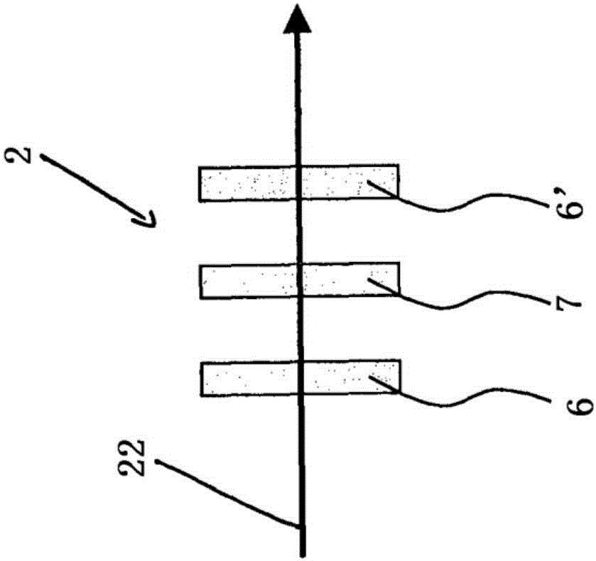
[0073] Figure 5 An inventive resonator configuration 100 utilizing the resonator 1 is shown. Figure 5 The resonators shown are ring resonators. Optionally, the resonator configuration 100 according to the present invention may also comprise linear resonators. exist Figure 6 A linear resonator is shown in .

[0074] Figure 5 The ring resonator 1 comprises a plurality of curved mirrors 3,13. Mirror 3 is an incoupling mirror configured to couple pump light P into. Mirror 3' is an outcoupling mirror for outcoupling laser light from resonator 1. The laser can be a CW laser (continuous wave) or a pulsed laser.

[0075] For some applications it is advantageous to have an active medium 24 in the resonator. The active medium 24 may be, for example, a laser active medium such as Ti:Sa crystal. Of course, other laser media are also contemplated. A deflection mirror 13 for beam guidance is provided in the resonator 1 . Thus, it may be useful to have some mirrors curved. Fo...


PUM


Abstract

The invention relates to a method for operating a laser device, comprising the steps: a) providing a laser pulse (110) in a resonator (1) so that the laser pulse (10) circulates in the resonator (1), the laser pulse (10) having a carrier wave (120); b) determining an offset frequency (f0) of the frequency comb corresponding to the laser pulse (110), the frequency comb having a plurality of laser modes (fm) at a distance (frep) from one another, the frequencies of which can be described by the formula: fm = m * frep + f0, m being a natural number; and c) varying the offset frequency (f0) by varying a geometric phase ([delta][phi]) that is impressed on the carrier wave (120) of the laser pulse (110) per resonator revolution.

Description

technical field [0001] The invention relates to the fields of methods for operating laser devices and optical resonator arrangements, respectively. The invention can be used particularly advantageously for the generation or fine tuning of frequency combs. It is also particularly advantageous to use the invention in combination with the generation of short or ultrashort laser pulses. For example, individual laser pulses may have a pulse duration in the picosecond or femtosecond range. However, other pulse durations such as larger or smaller pulse durations are also conceivable. Furthermore, pulse durations in the range of femtoseconds to nanoseconds are also advantageous. Background technique [0002] figure 1 a shows laser pulses expressed as electric field versus time. Both the envelope of the laser pulse 110 and the carrier wave 120 of the laser pulse 110 are shown. Carrier 120 is represented by a sinusoidal oscillation in the range of optical frequencies. [0003] ...

Claims


Application Information

Patent Timeline
Patent Type & Authority Applications(China)
IPC IPC(8): H01S3/10H01S3/13H01S3/00
CPCH01S3/0057H01S3/10061H01S3/1307H01S3/06791H01S3/08054H01S3/0816H01S3/0811H01S3/083H01S3/1625H01S3/1636H01S3/139H01S3/1067H01S3/107H01S3/1065H01S3/1112
Inventor 沃尔夫冈·汉塞尔T·斯坦梅茨M·费舍尔M·雷兹伍兹罗纳德·霍茨瓦尔特
Owner MENLO SYST
Why Eureka
Try Eureka