Molten steel casting device

A molten steel and sprue technology, applied in the field of molten steel casting devices, can solve problems such as complicated structure, short service life of equipment, lower mold clamping position and mold precision, and achieve safe and simple structure, high degree of automation and long service life Effect

Active Publication Date: 2018-12-18
MCC CAPITAL ENGINEERING & RESEARCH
View PDF6 Cites 0 Cited by
  • Summary
  • Abstract
  • Description
  • Claims
  • Application Information

AI Technical Summary

Problems solved by technology

[0004] However, the above-mentioned structure has the following disadvantages: (1) For cooling multiple molds with water-cooling technology, the waterway is increased, and the risk of pouring is increased, and water leakage on site is difficult to avoid, which is prone to safety accidents; (2) each The mold has six hydraulic locking cylinders. For multiple casting molds, the use of too many locking hydraulic cylinders will result in cumbersome structure and potential safety hazards; (3) For the connecting rod mechanism, too many frequent The use of excessive use will cause loosening of the joints, resulting in a reduction in the mold clamping position and mold accuracy, and a short service life of the equipment

Method used


Image

  • Molten steel casting device
  • Molten steel casting device
  • Molten steel casting device

Examples


Embodiment Construction

[0030] The following will clearly and completely describe the technical solutions in the embodiments of the present invention with reference to the accompanying drawings in the embodiments of the present invention. Obviously, the described embodiments are only some, not all, embodiments of the present invention. Based on the embodiments of the present invention, all other embodiments obtained by persons of ordinary skill in the art without making creative efforts belong to the protection scope of the present invention.

[0031] Except for the direction indicated by the separate definition, the directions of up and down mentioned in this article are all indicated by the present invention. figure 1 The upper and lower directions in the guideline shall prevail, which shall be explained together here.

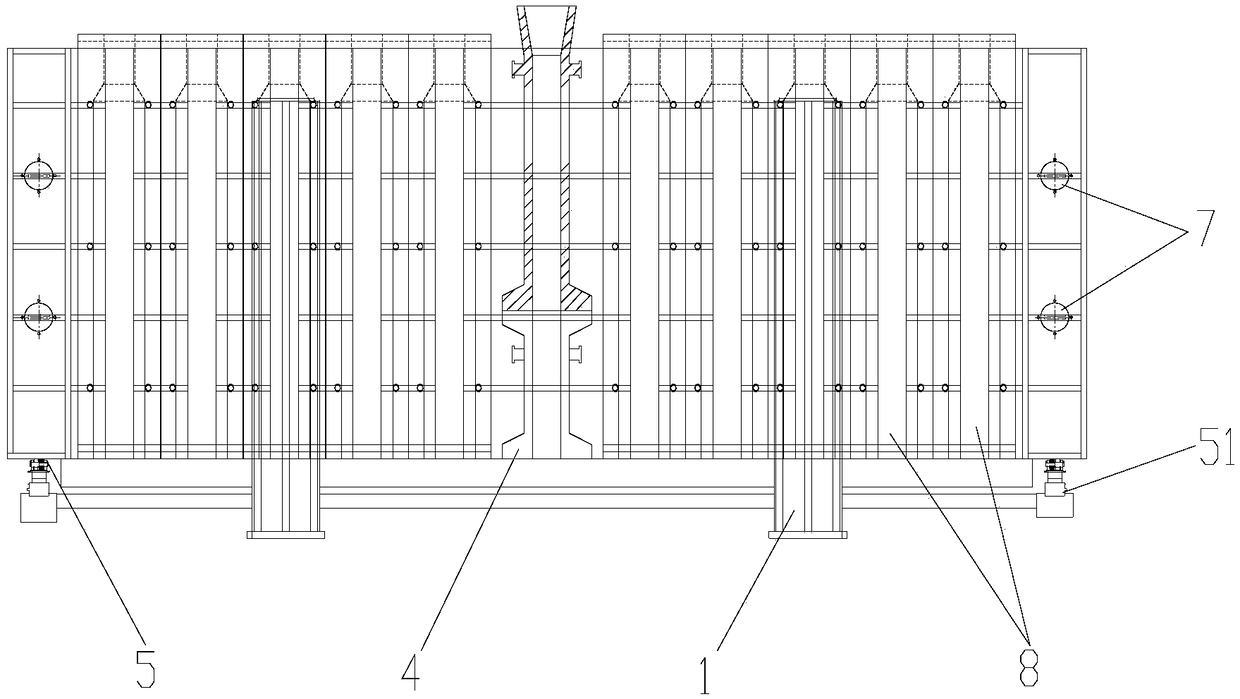
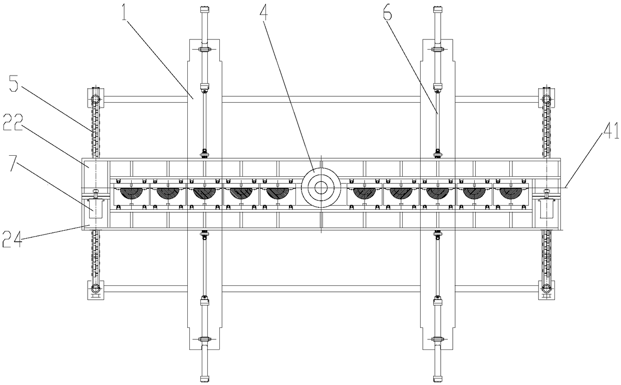
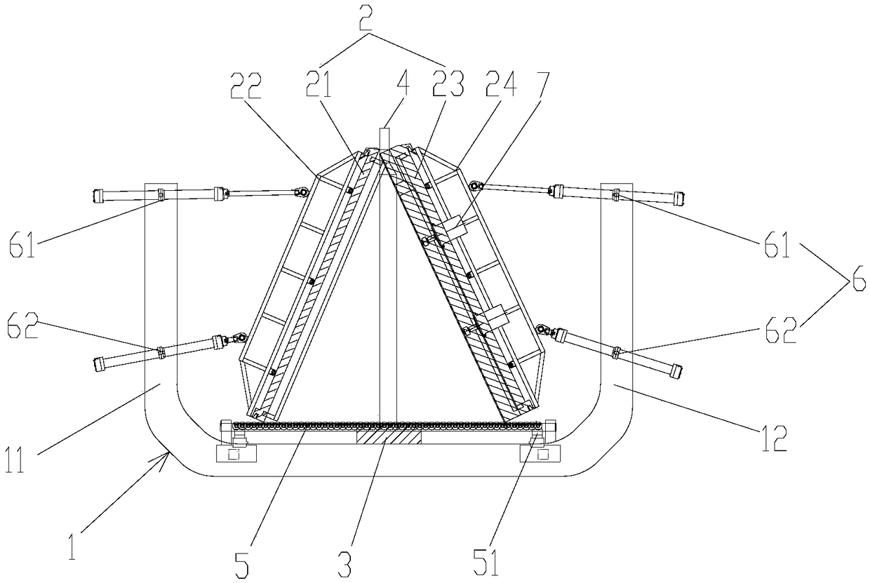
[0032] Such as Figure 1 to Figure 7 As shown, the present invention provides a molten steel casting device, which includes: at least two U-shaped frames 1, at least two U-shaped ...


PUM


Abstract

The invention provides a molten steel casting device. The molten steel casting device comprises two or more U-shaped frames, a mold body and a casting chassis. The two or more U-shaped frames are installed at intervals side by side, and a right stand column and a left stand column of each U-shaped frame are each provided with a set of driving hydraulic cylinders correspondingly. The mold body comprises a left mold bed and a right mold bed, the left mold bed is connected with the driving hydraulic cylinders installed on the left stand columns of all the U-shaped frames, and the right mold bed is connected with the driving hydraulic cylinders installed on the right stand columns of all the U-shaped frames; and the casting chassis is arranged on the two or more U-shaped frames horizontally, a casting passage is formed in the casting chassis, under the state that the left mold bed is attached with the right mold bed, the left mold bed and the right mold bed are locked by disc spring locking cylinders, the left mold bed, the right mold bed and the casting chassis are enclosed to form a plurality of pouring cavities, and the multiple pouring cavities all communicate with the casting passage. According to the molten steel casting device, casting of molten steel is achieved quickly and automatically, producing efficiency is improved, labor intensity is reduced, and the accident rate is reduced.

Description

technical field [0001] The invention relates to the field of casting, in particular to a molten steel casting device capable of realizing automatic rapid casting. Background technique [0002] The traditional split mold casting method mostly adopts wedge connection, that is, the two halves of the mold are connected by a T-shaped connecting block. There is a square hole on one side of the T-shaped connecting block, and the square hole is fixed with a trapezoidal wedge iron. During the process, the trapezoidal wedge irons are manually tapped to achieve fixation, resulting in high labor intensity, many safety accidents, and low production efficiency. Therefore, the traditional technology is in urgent need of improvement. [0003] At present, a kind of rapid casting machine for molten steel is also disclosed in the prior art, which adopts water flow on the back plate of the casting mold for cooling, and each mold in the molding mold is locked with six locking hydraulic oil cylin...

Claims


Application Information

Patent Timeline
Patent Type & Authority Patents(China)
IPC IPC(8): B22D7/08B22D7/12
CPCB22D7/08B22D7/12
Inventor 李耀军刘艳耿明山韩庆礼王蕾
Owner MCC CAPITAL ENGINEERING & RESEARCH
Why Eureka
Try Eureka