An electroplating passivation device

A technology of passivation and passivation solution, applied in the direction of metal material coating process, etc., can solve the problems of unreasonable structure of passivation product placement cylinder, low product qualification rate, increased production cost, etc., and achieve simple structure and simple device structure , high processing efficiency

Active Publication Date: 2018-09-21
浙江明泰控股发展股份有限公司
View PDF4 Cites 0 Cited by
  • Summary
  • Abstract
  • Description
  • Claims
  • Application Information

AI Technical Summary

Problems solved by technology

[0002] The existing electroplating passivation device moves at a constant speed after the jaws of the drive device catch the passivation product placement cylinder. When it reaches the passivation solution in the passivation tank, it will quickly go down and then move up. During this process, it will jump a few times. The screws or nuts or other products placed in the passivation product placement cylinder can be separated under small jumps, so that each surface can be uniformly passivated, but there are still shortcomings in the existing passivation pool: the existing The passivation tank is filled with passivation solution. When the passivation product placement cylinder is going down, the passivation solution at the position of the passivation product placement cylinder will flow to the outside and downward of the passivation cylinder, so that the passivation product placement cylinder During the beating process, due to the short time, some surfaces of the products stacked together will be unevenly passivated due to lack of passivation solution, and the pass rate of products will be low, resulting in increased production costs, and the structure of the passivated product placement cylinder is unreasonable, resulting in Low processing efficiency

Method used


Image

  • An electroplating passivation device
  • An electroplating passivation device

Examples


Embodiment Construction

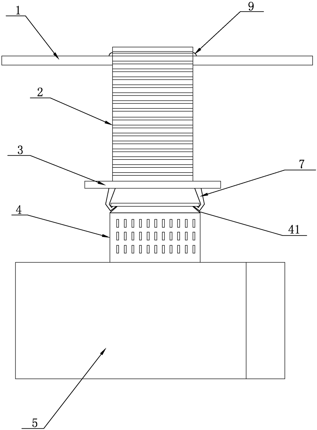
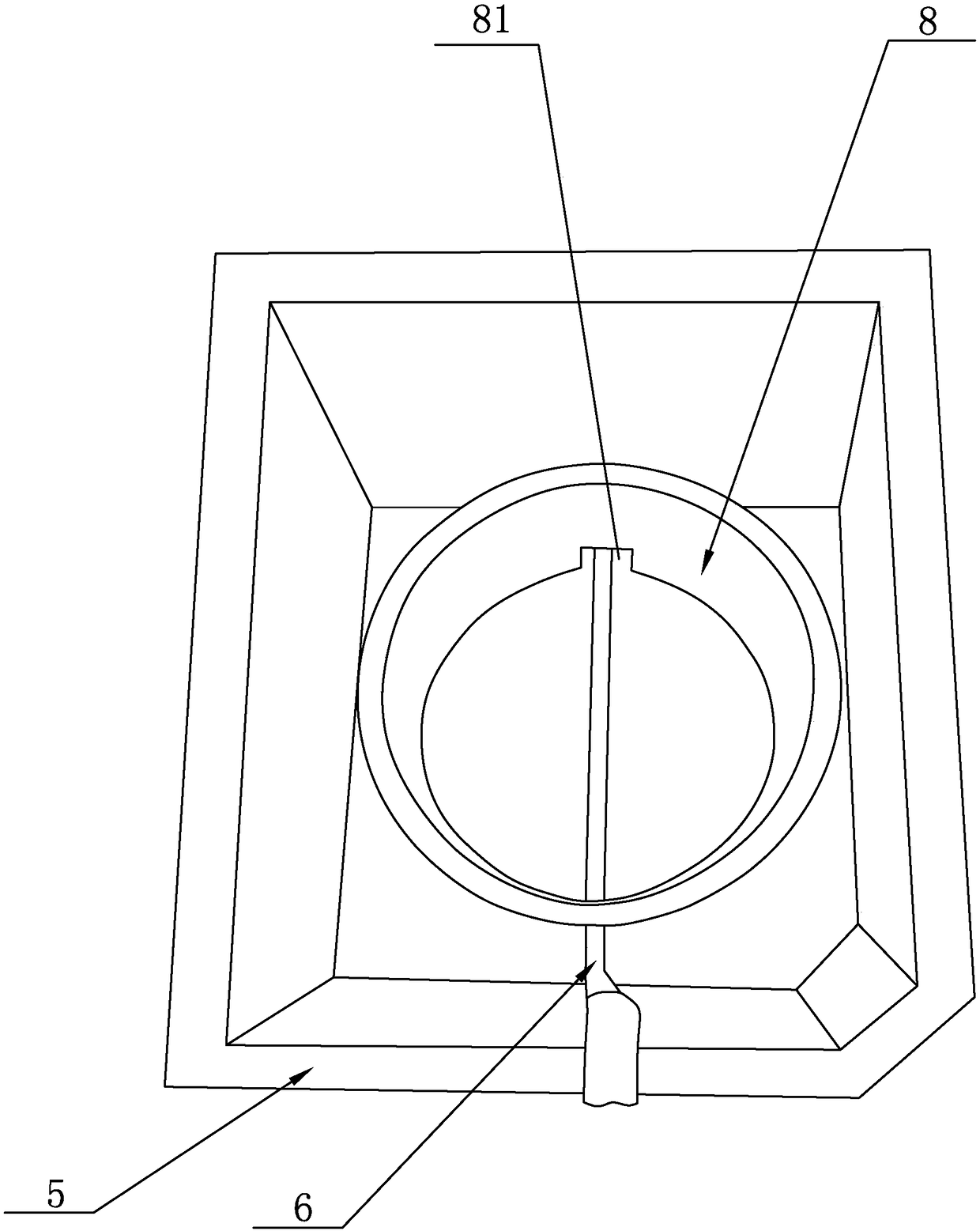
[0019] See figure 1 with figure 2 , The electroplating passivation device disclosed in the present invention includes a guide rail 1, a driving device 2, a connecting device 3, a passivation product placement cylinder 4, and a passivation tank 5, in which a passivation liquid delivery pipe is set 6. The guide rail 1 is arranged horizontally, the upper end of the driving device 2 is connected with the guide rail 1, and the lower end of the driving device 2 is connected with the connecting device 3, and the connecting device 3 is provided with a claw 7, and the passivation product is placed The lower end of the cylinder 4 is fixedly provided with a cylinder bottom, and a claw positioning groove 41 is provided on the outer wall surface of the upper end of the passivation product placement cylinder 4, and the connecting device 3 is clamped or separated from the claw positioning groove 41 through the claw 7; The passivation product placement cylinder 4 is located directly above the...


PUM


Abstract

The invention discloses an electroplating passivating device. The electroplating passivating device comprises a guide rail, a driving device, a connecting device, a passivated product placing barrel and a passivating pool, wherein the passivating pool is internally provided with a passivating liquid conveying pipe; the guide rail is transversely arranged; clamping jaws are arranged on the connecting device; a clamping jaw positioning groove is formed in the outer wall surface of the upper end of the passivated product placing barrel; the passivated product placing barrel is positioned over the passivating pool; the passivated product placing barrel is driven by the driving device to decline and sink into the passivating pool; a passivating liquid limiting guiding device for enabling passivating liquid to flow upwards is arranged on the bottom surface of the passivating pool at the position of the middle part; the passivating liquid limiting guiding device comprises a guiding cylinder, the guiding cylinder is vertically arranged, the height of the upper end face of the guiding cylinder is arranged to be lower than the upper end face of the passivating pool, and the lower end of the guiding cylinder is fixedly or detachably connected with the bottom surface of the passivating pool. Through the technical scheme, the electroplating passivating device is reasonable in structure set, simple in structure, convenient in operation, uniform in passivation for each surface of the product and high in processing efficiency.

Description

Technical field [0001] The invention relates to the technical field of passivation equipment, in particular to an electroplating passivation device. Background technique [0002] The existing electroplating passivation device uses the claws of the driving device to clamp the passivation product and move it at a constant speed. When it reaches the passivation solution in the passivation pool, it will quickly go down and then move up, and it will jump a few times in the process. The screws or nuts or other products placed in the passivation product placement cylinder can be separated under a small jump, so that each surface is uniformly passivated, but the existing passivation pool still has shortcomings: the existing The passivation tank is filled with passivation liquid. When the passivation product is placed in the barrel downwards, the passivation liquid at the position where the passivation product is placed will flow to the outside and downwards of the passivation barrel, so ...

Claims


Application Information

Patent Timeline
Patent Type & Authority Patents(China)
IPC IPC(8): C23C22/00
CPCC23C22/00
Inventor 吴金旺吴一阳吴也禹
Owner 浙江明泰控股发展股份有限公司
Why Eureka
Try Eureka