Water pump sealing mechanism

A technology of water pump sealing and water sealing, which is applied in the direction of engine sealing, pumps, pump components, etc., can solve the problems of high assembly process requirements, low assembly efficiency, complex structure, etc., achieve good results, improve production efficiency, and compact sealing structure Effect

Active Publication Date: 2019-04-02
CHONGQING SOKON IND GRP CO LTD
View PDF11 Cites 0 Cited by
  • Summary
  • Abstract
  • Description
  • Claims
  • Application Information

AI Technical Summary

Problems solved by technology

[0002] The cylinder of the automobile engine is equipped with a water jacket to cool the cylinder block. The cooling water in the water jacket circulates and cools the cylinder block under the drive of the water pump to ensure that the engine temperature will not be too high; and the power of the water pump is usually directly from the output power of the engine. The drive shaft drives the impeller in the water pump to rotate and then drives the cooling water circulation, and the two ends of the drive shaft respectively pass through the water chamber of the water pump and the oil chamber of the engine, so a shaft seal is arranged on the drive shaft. In the prior art, according to the water The properties of oil and oil require separate water seals and oil seals. The oil seal generally adopts a skeleton oil seal, while the water seal adopts a structure that matches the moving ring and the static ring. The structure of the water seal is relatively complicated, the volume is large, and the assembly process requires high requirements. low assembly efficiency,

Method used


Image

  • Water pump sealing mechanism
  • Water pump sealing mechanism

Examples


Embodiment Construction

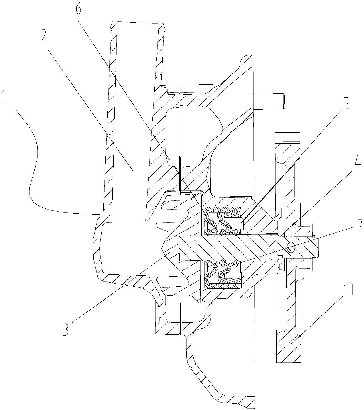
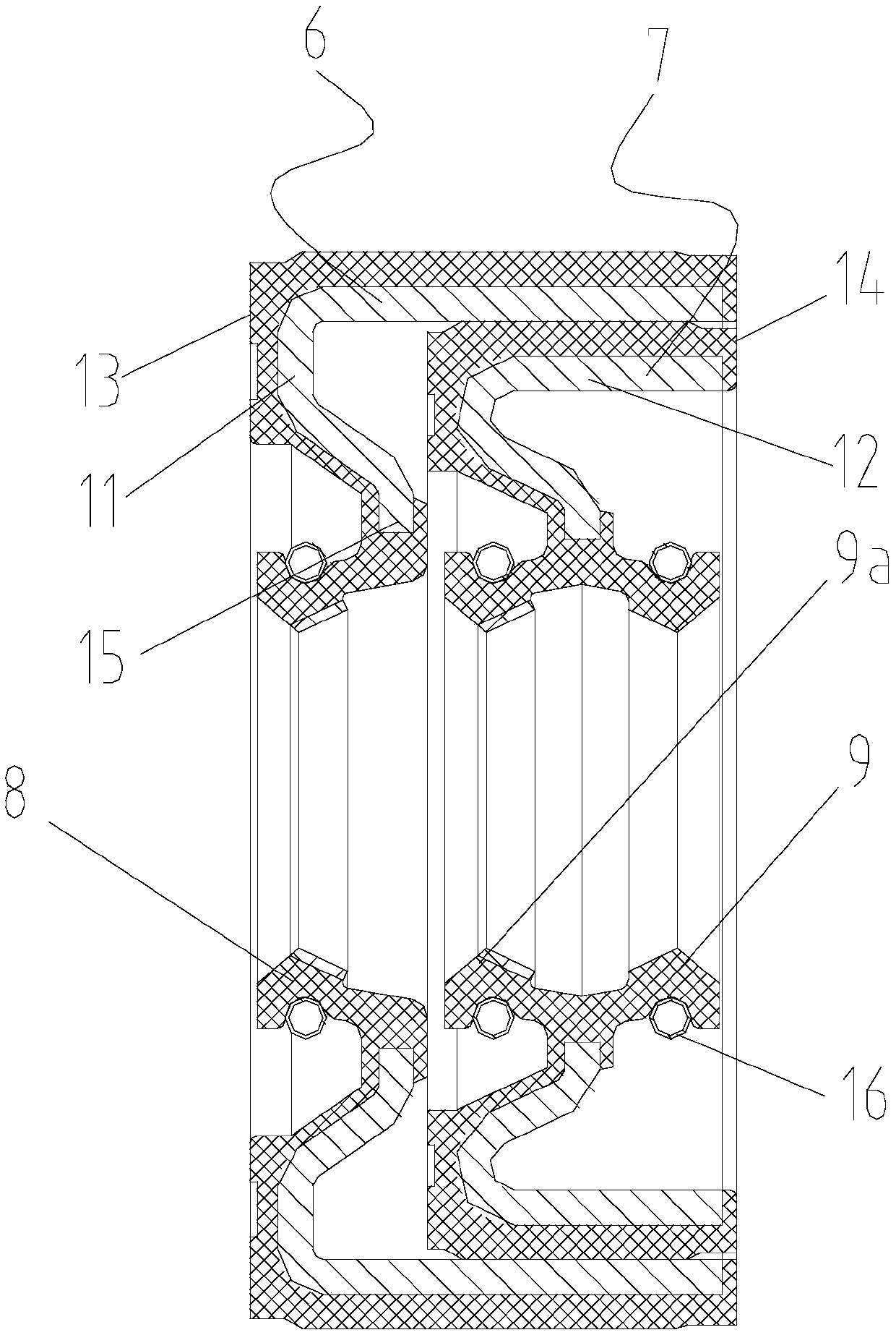
[0015] figure 1 It is a schematic diagram of the overall structure of the present invention, figure 2 It is a schematic diagram of the sealing structure of the present invention. As shown in the figure, the water pump sealing mechanism in this embodiment includes a water chamber 2 located in the water pump 1, a drive shaft 4 extending into the water chamber 2 for driving the impeller 3 of the water pump 1, The oil chamber 5 located outside the drive shaft 4 and the sealing device arranged between the water chamber 2 and the oil chamber 5 for sealing the shaft of the drive shaft 4; the sealing device includes a first skeleton water seal from the outside to the inside in the axial direction 6 and the second skeleton oil seal 7, the first skeleton water seal 6 is provided with a first lip 8 for sealing the water chamber 2, and the second skeleton oil seal 7 is provided with a second lip for sealing the oil chamber 5 mouth 9, the first lip 8 is provided with polytetrafluoroethyl...


PUM


Abstract

The invention discloses a sealing mechanism for a water pump. The sealing mechanism for the water pump comprises a water chamber positioned in the water pump, a driving shaft which extends into the water chamber and is used for driving an impeller of the water pump, an oil chamber positioned at the outer side of the driving shaft, and a sealing device which is arranged between the water chamber and the oil chamber and used for performing shaft sealing on the driving shaft; the sealing device comprises a first framework water seal and a second framework oil seal which are axially arranged from outside to inside; a first lip port for sealing the water chamber is arranged at the first framework water seal; a second lip port for sealing the oil chamber is arranged at the second framework oil seal; the first lip is provided with a polytetrafluoroethylene coating. According to the sealing mechanism for the water pump, the water chamber side is subjected to shaft sealing through the first lip port; the first lip port can be effectively prevented from being worn according to the wear resistance, the high temperature resistance and the low frictional coefficients of polytetrafluoroethylene, and moreover, the water sealing effect is good; the first framework oil seal is arranged at the oil chamber side and used for sealing the oil chamber; the sealing structure is compact, and the assembling is easy, so that the production efficiency can be improved.

Description

technical field [0001] The invention relates to the sealing field, in particular to a water pump sealing mechanism. Background technique [0002] The cylinder of the automobile engine is equipped with a water jacket to cool the cylinder block. The cooling water in the water jacket circulates and cools the cylinder block under the drive of the water pump to ensure that the engine temperature will not be too high; and the power of the water pump is usually directly from the output power of the engine. The drive shaft drives the impeller in the water pump to rotate and then drives the cooling water circulation, and the two ends of the drive shaft respectively pass through the water chamber of the water pump and the oil chamber of the engine, so a shaft seal is arranged on the drive shaft. In the prior art, according to the water The properties of oil and oil require separate water seals and oil seals. The oil seal generally adopts a skeleton oil seal, while the water seal adopt...

Claims


Application Information

Patent Timeline
Patent Type & Authority Patents(China)
IPC IPC(8): F16J15/3232F16J15/3252F16J15/40F04D29/12
CPCF04D29/126F16J15/3232F16J15/3252F16J15/40
Inventor 李飞扬郑炳方张春洲黄世明何家军
Owner CHONGQING SOKON IND GRP CO LTD
Why Eureka
Try Eureka