
Pressure wave signal generator and real-time tracking and positioning method for detector in pipe

A signal generator and internal detector technology, applied in pipeline systems, mechanical equipment, gas/liquid distribution and storage, etc., can solve the problems of low positioning accuracy, difficult real-time tracking and positioning of internal detection instruments, and environmental pollution.

Active Publication Date: 2017-03-15
SHENYANG POLYTECHNIC UNIV
View PDF5 Cites 12 Cited by
  • Summary
  • Abstract
  • Description
  • Claims
  • Application Information

AI Technical Summary

Problems solved by technology

If it is stuck in the pipeline for a long time, the fluid cannot be transported normally, which will cause huge economic losses and environmental pollution
[0003] The existing tracking and positioning technology for detection instruments in the pipeline may require external auxiliary information positioning, such as: fixed-point magnetic marker method, static magnetic field positioning method, radioactive ray positioning method, GPS / INS integrated navigation system positioning method, or the positioning accuracy is not high , such as: mileage wheel alignment method
Therefore, the existing tracer positioning technology is difficult to realize real-time tracking and positioning of the internal detection instrument in the pipeline

Method used


Image

  • Pressure wave signal generator and real-time tracking and positioning method for detector in pipe
  • Pressure wave signal generator and real-time tracking and positioning method for detector in pipe
  • Pressure wave signal generator and real-time tracking and positioning method for detector in pipe

Examples


Embodiment Construction

[0063] The specific implementation manners of the present invention will be described in detail below in conjunction with the accompanying drawings.

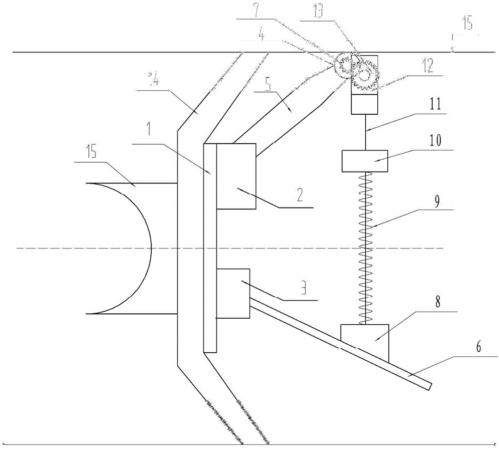
[0064] This embodiment provides a figure 1 The pressure wave signal generator shown is installed on the flange 1 of the detector in the pipeline, and the pressure wave signal generator generates a pressure wave signal when the detector in the pipeline advances inside the pipeline;

[0065] The pressure wave signal generator includes: power take-off wheel 4, support arm 5, swing arm 6, first gear 7, releaser 8, spring 9, kinematic pair 10, screw rod 11, reducer 12, second gear 13;

[0066] The first support point 2 and the second support point 3 are set on the flange 1 of the detector in the pipeline. 6 is equipped with a release device 8, the release device 8 is connected with the kinematic pair 10 through the spring 9, the kinematic pair 10 is connected with the reducer 12 through the screw rod 11, the first gear 7 is installe...


PUM


Abstract

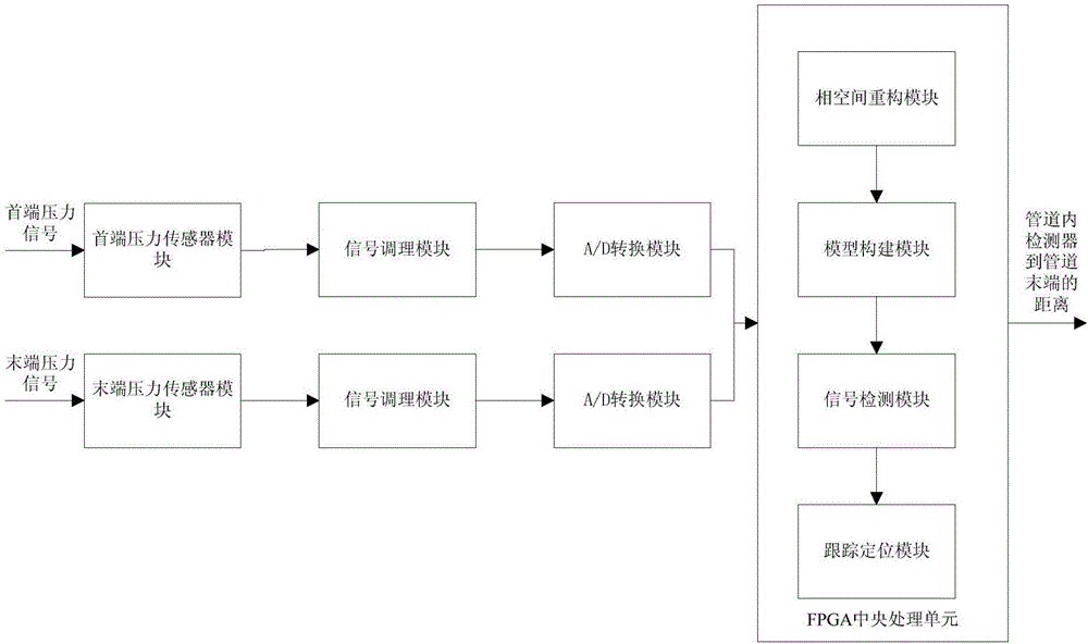
The invention provides a pressure wave signal generator and a real-time tracking and positioning method for a detector in a pipe. The pressure wave signal generator is arranged on a flange of the detector in the pipe, and the pressure wave signal generator generates signals when the pressure wave signal generator advances in the pipe along with the detector in the pipe; and the pressure wave signal generator comprises a power take-off gear, a supporting arm, a swinging arm, a first gear, a releaser, a spring, a movement pair, a screw rod, a reducer and a second gear. The method comprises the following steps that real-time pressure signals of the head end of the pipe and the tail end of the pipe are collected, and phase-space reconstruction is conducted; a pressure wave chaos state prediction model is constructed and trained, and a pressure wave chaos state real-time model and a pressure wave chaos state synchronous model are synchronously constructed; the arrival time of the pressure wave signals generated by the pressure wave signal generator to the head end of the pipe and the arrival time of the pressure wave signals generated by the pressure wave signal generator to the tail end of the pipe are detected; and the distance between the detector in the pipe and the tail end of the pipe is calculated. According to the pressure wave signal generator and the real-time tracking and positioning method for the detector in the pipe, real-time tracking and blockage positioning of the detector in the pipe are achieved, the tracking range is large, and the pressure wave signal generator and the real-time tracking and positioning method for the detector in the pipe are not limited by the buried depth of the pipe and the thickness of the pipe wall.

Description

technical field [0001] The invention belongs to the technical field of pipeline detection, and in particular relates to a real-time tracking and positioning method for a pressure wave signal generator and a detector in a pipeline. Background technique [0002] With the increase of energy demand, pipeline transportation, as the main transportation mode of oil and gas energy, has been widely used all over the world due to its irreplaceable outstanding advantages. At the same time, the safety of pipeline transportation has become increasingly popular. The governments of various countries attach great importance to it. Due to the danger and pollution of the transported medium, once an accident occurs, it will cause huge loss of life and property and environmental pollution. Pipeline accident detection is one of the important problems that need to be solved in the fields of petroleum, chemical industry, natural gas, etc., and in-pipeline detection is an important method for pipel...

Claims


Application Information

Patent Timeline
IPC IPC(8): F17D5/02
CPCF17D5/02
Inventor 汪泽松宋华东韩科
Owner SHENYANG POLYTECHNIC UNIV
Learn More